Ga door naar hoofdinhoud

MacBook Pro 15" Unibody Early 2011 Logic Board Replacement

Alleen vereisten
Deze handleiding is alleen bedoeld als vereiste voor andere handleidingen. Het staat niet op zichzelf.

Wat je nodig hebt

  1. MacBook Pro 15" Unibody Early 2011 Logic Board Replacement, Logic Board: stap 1, afbeelding 1 van 1
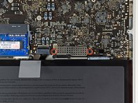
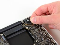
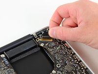
    • Use the flat end of a spudger to lift the right fan connector out of its socket on the logic board.

    • It is useful to twist the spudger axially from beneath the fan cable wires to release the connector.

  2. MacBook Pro 15" Unibody Early 2011 Logic Board Replacement: stap 2, afbeelding 1 van 2 MacBook Pro 15" Unibody Early 2011 Logic Board Replacement: stap 2, afbeelding 2 van 2
    • Remove the three 3.4 mm (3.1 mm) T6 Torx screws securing the right fan to the logic board.

    • Lift the right fan out of its opening in the logic board.

  3. MacBook Pro 15" Unibody Early 2011 Logic Board Replacement: stap 3, afbeelding 1 van 1
    • Pull the camera cable out of its socket on the logic board.

    • Don't lift upward on the camera cable as you disconnect it. Pulling upward on the cable may damage both the cable and the logic board. Pull the cable parallel to the face of the logic board.

  4. MacBook Pro 15" Unibody Early 2011 Logic Board Replacement: stap 4, afbeelding 1 van 1
    • Use the flat end of a spudger to pry the AirPort/Bluetooth connector up from its socket on the logic board.

  5. MacBook Pro 15" Unibody Early 2011 Logic Board Replacement: stap 5, afbeelding 1 van 1
    • Use the flat end of a spudger to lift the optical drive connector out of its socket on the logic board.

  6. MacBook Pro 15" Unibody Early 2011 Logic Board Replacement: stap 6, afbeelding 1 van 1
    • Disconnect the hard drive/IR sensor cable from its socket on the logic board by lifting up from beneath its connector.

  7. MacBook Pro 15" Unibody Early 2011 Logic Board Replacement: stap 7, afbeelding 1 van 1
    • Use the flat end of a spudger to lift the subwoofer/right speaker connector out of its socket on the logic board.

    • Pry up from beneath the wires.

  8. MacBook Pro 15" Unibody Early 2011 Logic Board Replacement: stap 8, afbeelding 1 van 2 MacBook Pro 15" Unibody Early 2011 Logic Board Replacement: stap 8, afbeelding 2 van 2
    • Remove the two 1.5 mm ( 1.2 mm ) Phillips screws securing the keyboard/trackpad cable cover to the logic board.

    • Lift the cover off the logic board and set it aside.

  9. MacBook Pro 15" Unibody Early 2011 Logic Board Replacement: stap 9, afbeelding 1 van 1
    • Use the flat end of a spudger to pry the trackpad connector up and out of its socket on the logic board.

  10. MacBook Pro 15" Unibody Early 2011 Logic Board Replacement: stap 10, afbeelding 1 van 2 MacBook Pro 15" Unibody Early 2011 Logic Board Replacement: stap 10, afbeelding 2 van 2
    • Use your fingernail to flip up the retaining flap on the keyboard ribbon cable ZIF socket.

    • Be sure you are prying up on the hinged retaining flap, not the socket itself.

    • Use the tip of a spudger to pull the keyboard ribbon cable out of its socket.

  11. MacBook Pro 15" Unibody Early 2011 Logic Board Replacement: stap 11, afbeelding 1 van 1
    • Use the flat end of a spudger to lift the battery indicator connector up and out of its socket on the logic board.

  12. MacBook Pro 15" Unibody Early 2011 Logic Board Replacement: stap 12, afbeelding 1 van 2 MacBook Pro 15" Unibody Early 2011 Logic Board Replacement: stap 12, afbeelding 2 van 2
    • Grab the plastic pull tab secured to the display data cable lock and rotate it toward the DC-In side of the computer.

    • Pull the display data cable straight out of its socket on the logic board.

    • Do not lift up on the display data cable, as its socket is very fragile. Pull the cable parallel to the face of the logic board.

  13. MacBook Pro 15" Unibody Early 2011 Logic Board Replacement: stap 13, afbeelding 1 van 2 MacBook Pro 15" Unibody Early 2011 Logic Board Replacement: stap 13, afbeelding 2 van 2
    • Use the tip of a spudger to flip up the retaining flap on the keyboard backlight ribbon cable ZIF socket.

    • Be sure you are flipping up the hinged retaining flap, not the socket itself.

    • Pull the keyboard backlight ribbon cable out of its socket.

  14. MacBook Pro 15" Unibody Early 2011 Logic Board Replacement: stap 14, afbeelding 1 van 1
    • Remove the following nine screws:

    • Seven 3.4 mm ( 3.1 mm) T6 Torx screws on the logic board

    • Two 8 mm T6 Torx screws on the DC-In board

  15. MacBook Pro 15" Unibody Early 2011 Logic Board Replacement: stap 15, afbeelding 1 van 3 MacBook Pro 15" Unibody Early 2011 Logic Board Replacement: stap 15, afbeelding 2 van 3 MacBook Pro 15" Unibody Early 2011 Logic Board Replacement: stap 15, afbeelding 3 van 3
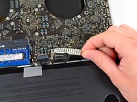
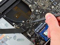
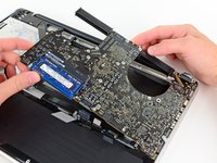
    • Carefully lift the logic board assembly from its left side and work it out of the upper case, minding the optical drive cable and the I/O ports that may get caught during removal.

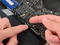
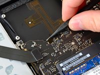
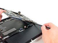
    • If necessary, use the flat end of a spudger to separate the microphone from the upper case.

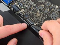
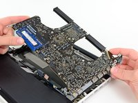
    • Pull the I/O port side of the logic board away from the side of the upper case and remove the logic board assembly.

Conclusie

To reassemble your device, follow these instructions in reverse order.

Één andere persoon heeft deze handleiding voltooid.

Één opmerking

Should a person be using an ESD wristband or anti-static mat when doing this? I didn’t use one and now I’m worried.

Nick Doe - Antwoord

Voeg opmerking toe

Weergavestatistieken:

Afgelopen 24 uren: 0

Afgelopen 7 dagen: 0

Afgelopen 30 dagen: 0

Altijd: 1,749