Deze versie kan foutieve bewerkingen bevatten. Schakel over naar de recentste gecontroleerde momentopname.
Wat je nodig hebt
-
Deze stap is niet vertaald. Help het te vertalen
-
Hold the end of the cable retainer down with one finger while you use the tip of a spudger to slightly lift the other end and rotate it away from the camera cable connector.
-
-
Deze stap is niet vertaald. Help het te vertalen
-
Disconnect the camera cable by pulling the male end straight away from its socket.
-
-
Deze stap is niet vertaald. Help het te vertalen
-
Use the flat end of a spudger to pry the optical drive cable connector up off the logic board.
-
-
Deze stap is niet vertaald. Help het te vertalen
-
Using the flat end of a spudger, pry the subwoofer connector straight up off the logic board.
-
-
Deze stap is niet vertaald. Help het te vertalen
-
Use the flat end of a spudger to pry the hard drive/IR sensor cable connector up off the logic board.
-
-
-
Deze stap is niet vertaald. Help het te vertalen
-
Remove the two 1.5 mm Phillips screws securing the cable cover to the logic board.
-
Lift the cable cover out of the upper case.
-
-
Deze stap is niet vertaald. Help het te vertalen
-
Use a spudger to pry the trackpad flex ribbon cable connector up off the logic board.
-
-
Deze stap is niet vertaald. Help het te vertalen
-
Using the tip of a spudger, flip up the keyboard ribbon cable retaining flap.
-
Pull the keyboard ribbon cable straight out of its socket.
-
-
Deze stap is niet vertaald. Help het te vertalen
-
Use a spudger to pry the battery indicator ribbon cable connector up off the logic board.
-
-
Deze stap is niet vertaald. Help het te vertalen
-
Remove the single 7 mm Phillips screw securing the display data cable retainer to the upper case.
-
Remove the display data cable retainer from the upper case.
-
-
Deze stap is niet vertaald. Help het te vertalen
-
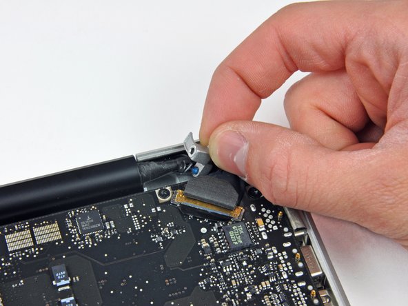
Grab the plastic pull tab secured to the display data cable lock and rotate it toward the DC-in side of the computer.
-
Pull the display data cable connector straight away from its socket.
-
-
Deze stap is niet vertaald. Help het te vertalen
-
Using the tip of a spudger, flip up the keyboard backlight ribbon cable retaining flap.
-
Pull the keyboard backlight ribbon cable straight out of its socket.
-
-
Deze stap is niet vertaald. Help het te vertalen
-
Remove the following screws:
-
Eight 3.5 mm T6 Torx screws securing the logic board to the upper case.
-
Two T6 Torx screws securing the DC-In board to the upper case.
-
-
Deze stap is niet vertaald. Help het te vertalen
-
Carefully lift the logic board assembly from the left side and work it out of the upper case, minding the port side that may get caught during removal.
-
-
Deze stap is niet vertaald. Help het te vertalen
-
Lift the logic board enough to gain clearance and use a spudger to pry the microphone up off the upper case.
-
Slide the logic board away from the port openings and lift the assembly out of the upper case.
-