Deze versie kan foutieve bewerkingen bevatten. Schakel over naar de recentste gecontroleerde momentopname.
Wat je nodig hebt
-
Deze stap is niet vertaald. Help het te vertalen
-
Use your fingers to push both battery release tabs away from the battery, and lift the battery out of the computer.
-
-
Deze stap is niet vertaald. Help het te vertalen
-
Remove the three identical Phillips screws from the memory door.
-
-
Deze stap is niet vertaald. Help het te vertalen
-
Lift the memory door up enough to get a grip on it, and slide it toward you, pulling it away from the casing.
-
-
Deze stap is niet vertaald. Help het te vertalen
-
Remove the two Phillips screws in the battery compartment near the latch.
-
-
Deze stap is niet vertaald. Help het te vertalen
-
Remove the following 6 screws:
-
Two 10 mm T6 Torx screws on either side of the RAM slot.
-
Four 14.5 mm Phillips screws along the hinge.
-
-
Deze stap is niet vertaald. Help het te vertalen
-
Remove the four Phillips screws on the port side of the computer.
-
-
Deze stap is niet vertaald. Help het te vertalen
-
Rotate the computer 90 degrees and remove the two Phillips screws from the rear of the computer.
-
-
Deze stap is niet vertaald. Help het te vertalen
-
Rotate the computer 90 degrees again and remove the four Phillips screws from the side of the computer.
-
-
Deze stap is niet vertaald. Help het te vertalen
-
Lift up at the rear of the case and work your fingers along the sides, freeing the case as you go. Once you have freed the sides, you may need to rock the case up and down to free the front of the upper case. This stage can be quite tricky. Over the DVD reader are 4 tabs set back which pull out vertically.
-
Note that the two small tongues on the left hand front of the upper case may bend while you remove the upper case. When re-installing, you may need to bend them back to fit in the grooves in the lower case.
-
-
Deze stap is niet vertaald. Help het te vertalen
-
Disconnect the trackpad and keyboard ribbon cable from the logic board, removing tape as necessary.
-
Remove the upper case.
-
-
-
Deze stap is niet vertaald. Help het te vertalen
-
Disconnect the iSight, inverter, and left fan cables from the logic board.
-
-
Deze stap is niet vertaald. Help het te vertalen
-
Use a spudger to flip up the brown plastic flap securing the left ambient light sensor cable to the logic board.
-
Slide the left ambient light sensor cable to the left and out of its connector.
-
-
Deze stap is niet vertaald. Help het te vertalen
-
Peel up the left ambient light sensor cable from above the left fan.
-
-
Deze stap is niet vertaald. Help het te vertalen
-
Peel up the iSight and inverter cables from above the left fan, removing tape as necessary.
-
-
Deze stap is niet vertaald. Help het te vertalen
-
Remove the following 3 screws:
-
One 6.2 mm black T6 Torx screw from the right side of the fan.
-
Two 9.4 mm silver T6 Torx screws from the left side of the fan.
-
-
Deze stap is niet vertaald. Help het te vertalen
-
Lift the lift fan up and carefully peel up the tape securing the fan to the heat sink as you go.
-
-
Deze stap is niet vertaald. Help het te vertalen
-
Disconnect the hard drive and ExpressCard connectors from the left side of the logic board.
-
-
Deze stap is niet vertaald. Help het te vertalen
-
Disconnect the two antenna cables attached to the Airport Extreme card.
-
-
Deze stap is niet vertaald. Help het te vertalen
-
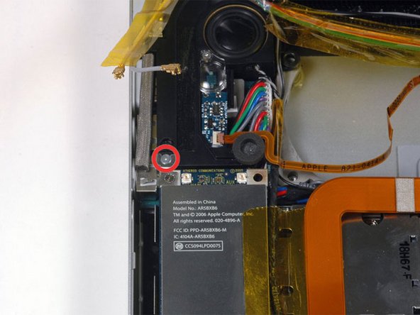
Remove the single silver Phillips screw located just above the Airport Extreme card.
-
Lift the small silver metal retaining bracket up and out of the computer.
-
-
Deze stap is niet vertaald. Help het te vertalen
-
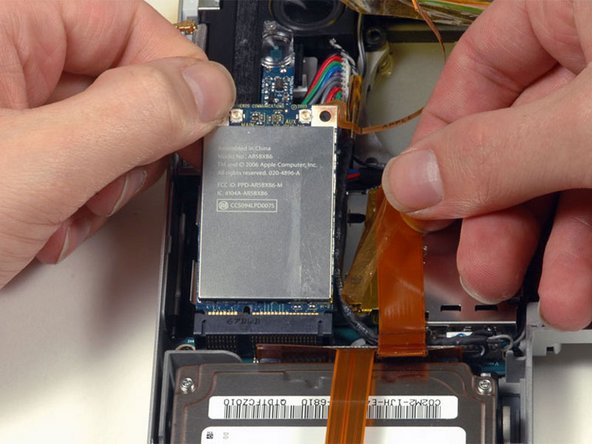
Peel back the orange tape on the right side of the Airport Extreme card.
-
Lift the Airport Extreme card up and slide it out of its connector.
-
-
Deze stap is niet vertaald. Help het te vertalen
-
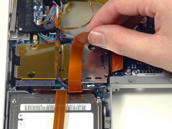
Peel up the orange hard drive cable from above the ExpressCard cage.
-
-
Deze stap is niet vertaald. Help het te vertalen
-
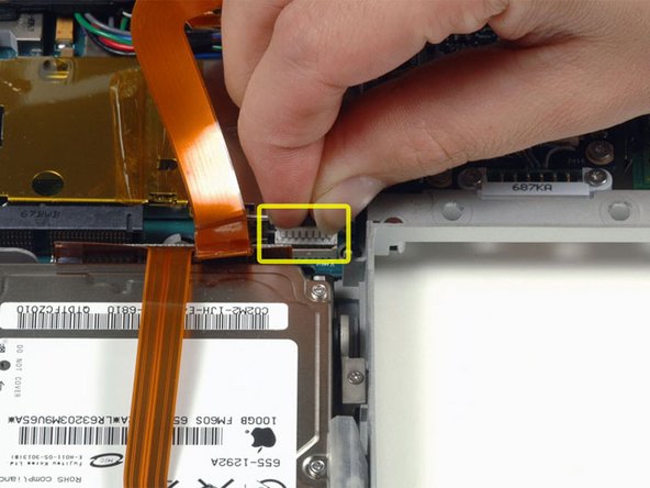
Disconnect the speaker cable from the corner of the left I/O board.
-
-
Deze stap is niet vertaald. Help het te vertalen
-
Remove the single black T6 Torx screw securing the left speaker.
-
-
Deze stap is niet vertaald. Help het te vertalen
-
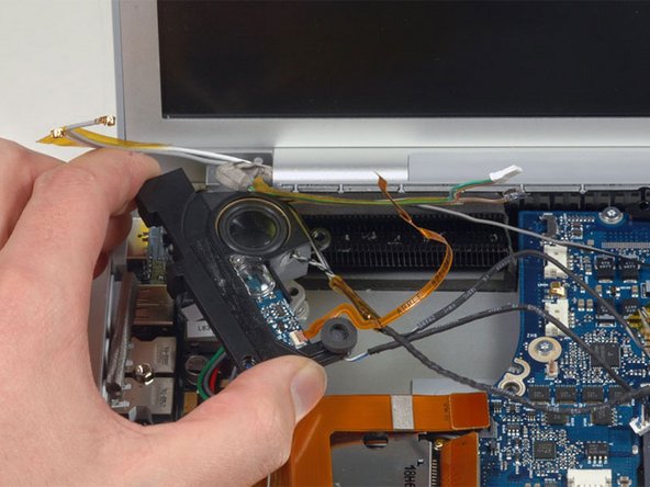
Lift the left speaker assembly out of its housing and place it in the area previously occupied by the left fan.
-
-
Deze stap is niet vertaald. Help het te vertalen
-
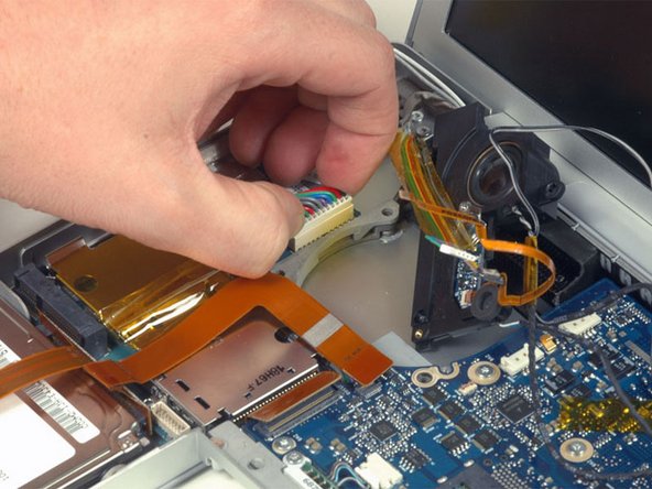
Disconnect the large multi-colored power cable from the left I/O board.
-
-
Deze stap is niet vertaald. Help het te vertalen
-
Remove the following 5 screws/standoffs:
-
Four black T6 Torx screws securing the left I/O board to the lower case.
-
One 4 mm standoff located between the audio jacks.
-
-
Deze stap is niet vertaald. Help het te vertalen
-
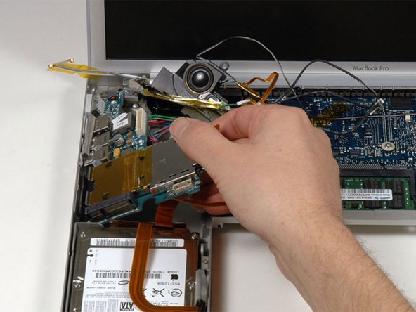
Lift up the right side of the left I/O board and slide it out of the computer.
-
-
Deze stap is niet vertaald. Help het te vertalen
-
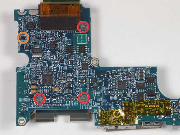
Remove the following 4 screws:
-
Three 1.2 mm silver Phillips with large heads.
-
One 3.2 mm black Phillips on the left side.
-


Annuleren: ik heb deze handleiding niet afgemaakt.
Één andere persoon heeft deze handleiding voltooid.
