Deze versie kan foutieve bewerkingen bevatten. Schakel over naar de recentste gecontroleerde momentopname.
Wat je nodig hebt
-
Deze stap is niet vertaald. Help het te vertalen
-
Use your fingers to push both battery release tabs away from the battery, and lift the battery out of the computer.
-
-
Deze stap is niet vertaald. Help het te vertalen
-
Remove the three identical 2mm Phillips screws from the memory door.
-
Lift the memory door up enough to grip it and slide it toward you, pulling it away from the casing.
-
-
Deze stap is niet vertaald. Help het te vertalen
-
Remove the two 2.8 mm Phillips screws in the battery compartment near the latch.
-
-
Deze stap is niet vertaald. Help het te vertalen
-
Remove the following 6 screws:
-
Two 10 mm T6 Torx screws on either side of the RAM slot.
-
Four 14.5 mm Phillips screws along the hinge.
-
-
-
Deze stap is niet vertaald. Help het te vertalen
-
Remove the four 3.2 mm PH00 Phillips screws on the port side of the computer.
-
-
Deze stap is niet vertaald. Help het te vertalen
-
Rotate the computer 90 degrees and remove the two 3.2 mm Phillips screws from the rear of the computer.
-
-
Deze stap is niet vertaald. Help het te vertalen
-
Rotate the computer 90 degrees again and remove the four 3.2 mm Phillips screws from the side of the computer.
-
-
Deze stap is niet vertaald. Help het te vertalen
-
Lift up at the rear of the case and work your fingers along the sides, freeing the case as you go. Once you have freed the sides, you may need to rock the case up and down to free the front of the upper case.
-
There are four plastic clips above the DVD slot, and another above and to the left of the IR sensor. These clips can be very difficult to disengage without prying. They can also be difficult to re-engage during reassembly.
-
-
Deze stap is niet vertaald. Help het te vertalen
-
Disconnect the trackpad and keyboard ribbon cable from the logic board, removing tape as necessary.
-
Remove the upper case.
-
-
Deze stap is niet vertaald. Help het te vertalen
-
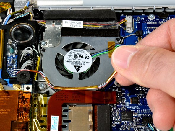
Disconnect the left ambient light sensor cable from the logic board by placing a spudger beneath the connector and lifting up.
-
Peel up the left ambient light sensor cable from above the left fan, removing tape as necessary.
-
-
Deze stap is niet vertaald. Help het te vertalen
-
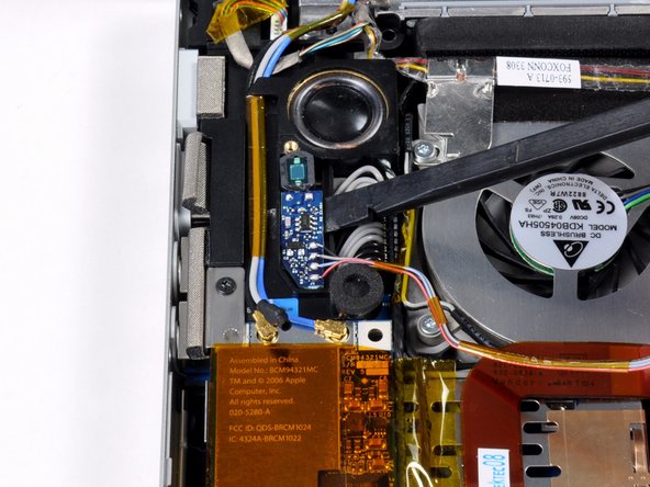
Remove the single silver Phillips screw securing the clear plastic shield over the left ambient light sensor.
-
Lift the clear plastic shield off the left ambient light sensor.
-
Use a spudger to pry the left ambient light sensor board out of its housing on the left speaker.
-
Lift the left ambient light sensor board out of the computer.
-


Annuleren: ik heb deze handleiding niet afgemaakt.
3 andere personen hebben deze handleiding voltooid.

2 opmerkingen
Do you know what each wire from the ALS does? Previous owner broke the connector socket off the logic board; now the computer thinks it’s always in maximum ambient light, so the keyboard backlight is disabled. Wondering if I can hardwire 2 pins together on the logic board to make it think it’s in minimum ambient light, so I can control the keyboard backlight manually. Thanks!!
I found a much easier solution: There is a free app called LabTick that allows you to adjust the keyboard illumination regardless of input from the ALS.