Deze versie kan foutieve bewerkingen bevatten. Schakel over naar de recentste gecontroleerde momentopname.
Wat je nodig hebt
-
-
Verwijder de volgende tien schroeven:
-
Drie 14.4 mm lange Phillips #00 schroeven
-
Drie 3.5 mm lange Phillips #00 schroeven
-
Vier 3.5 mm lange geschouderde Phillips #00 schroeven
-
-
-
Gebruik de voor- of achterkant van een spudger om de batterijaansluiting uit het contact op het moederbord omhoog te wrikken.
-
-
Deze stap is niet vertaald. Help het te vertalen
-
Use the edge of a spudger to gently pry the fan connector up and out of its socket on the logic board.
-
-
Deze stap is niet vertaald. Help het te vertalen
-
Remove the following three screws securing the fan to the logic board:
-
One 7.2 mm T6 Torx screw
-
Two 5.3 mm T6 Torx screws
-
-
Deze stap is niet vertaald. Help het te vertalen
-
Lift the fan out of its recess in the logic board, minding its cable that may get caught.
-
-
-
Deze stap is niet vertaald. Help het te vertalen
-
Use the tip of a spudger to pull the right speaker/subwoofer cable out from under the retaining finger molded into the upper case.
-
Pull the right speaker/subwoofer cable upward to lift the connector out of its socket on the logic board.
-
-
Deze stap is niet vertaald. Help het te vertalen
-
Disconnect the following four cables:
-
AirPort/Bluetooth cable
-
Optical drive cable
-
Hard drive cable
-
Trackpad cable
-
-
Deze stap is niet vertaald. Help het te vertalen
-
Use your fingernail to flip up the retaining flap on the keyboard ribbon cable ZIF socket.
-
Use the tip of a spudger to pull the keyboard ribbon cable out of its socket.
-
-
Deze stap is niet vertaald. Help het te vertalen
-
If present, remove the small strip of black tape covering the keyboard backlight cable socket.
-
-
Deze stap is niet vertaald. Help het te vertalen
-
Use the tip of a spudger or your fingernail to flip up the retaining flap on the keyboard backlight ribbon cable ZIF socket.
-
Pull the keyboard backlight ribbon cable out of its socket.
-
-
Deze stap is niet vertaald. Help het te vertalen
-
Use the flat end of a spudger to pry the sleep sensor/battery indicator connector up from its socket on the logic board.
-
-
Deze stap is niet vertaald. Help het te vertalen
-
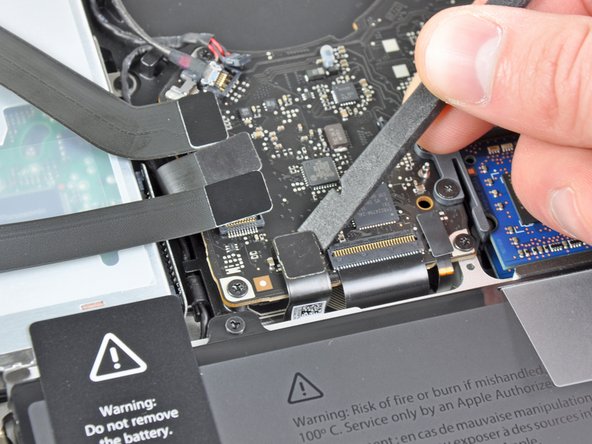
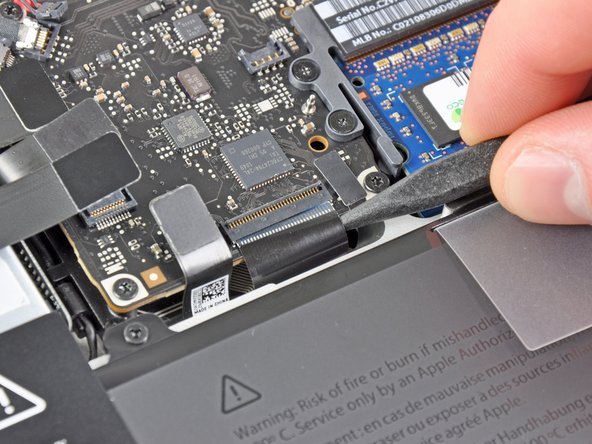
Grab the plastic pull tab secured to the display data cable lock and rotate it toward the DC-In side of the computer.
-
Pull the display data cable straight out of its socket on the logic board.
-
-
Deze stap is niet vertaald. Help het te vertalen
-
Remove the following nine screws:
-
Five 3.6 mm T6 Torx screws
-
Two 4.3 mm T6 Torx screws
-
Two 7.2 mm T6 Torx screws
-
Five 3.0 mm T6 screws
-
Two 3.6 mm T6 screws
-
Two 6.7 mm T6 screws
-
-
Deze stap is niet vertaald. Help het te vertalen
-
Remove the following two screws:
-
One 8.6 mm Phillips screw
-
One 5.5 mm Phillips screw
-
Remove the display data cable retainer from the upper case.
-
-
Deze stap is niet vertaald. Help het te vertalen
-
Use the tip of a spudger to gently peel the microphone off the adhesive securing it to the upper case.
-
-
Deze stap is niet vertaald. Help het te vertalen
-
Minding the many connectors near its edges, lift the logic board from the end nearest the optical drive.
-
Without flexing the board, maneuver it out of the upper case, minding the flexible connection to the DC-In board that may get caught in the upper case.
-
Remove the logic board.
-
-
Deze stap is niet vertaald. Help het te vertalen
-
Remove the three 8.4 mm #1 Phillips screws securing the heat sink to the logic board.
-
Annuleren: ik heb deze handleiding niet afgemaakt.
98 andere personen hebben deze handleiding voltooid.
17 opmerkingen
Awesome guide, I was able to complete the whole job (very slowly and carefully) in an hour start to finish. I am not an expert, I am just your average, everyday DIYer. I'm actually a medical student with an interest in engineering and "tinkering" looking to save money however I can. I would HIGHLY recommend this to every one of my friends (and I may even do this for some people). My keyboard doesn't get warm anymore, and my fan stays quieter doing more things. I'm now running 40-45 degree temps instead of 70-85 temps. Incredible. Like others on the internet, my computer had a TON of paste on it that was all over the CPU. I feel better now that I know how my computer was put together (by me). Good luck!
I also reapplied thermal paste under the heatsink on my early 2011 Macbook Pro. Temps are on average much lower, now my cpu almost never spikes above 70 C. I used the mac application Hardware Monitor to check temps in real time before and after. Previously doing pretty much anything on my MBP would cause the fan to spin at its max rpm and the computer was almost always hot to the touch. Now it's silent (also swapped the hdd for an ssd) and the fans almost never turn on at all!
I followed the guide after my MBP began showing extreme CPU temps like 95-98 C.
I removed all the dry paste that was left on top of the CPU, and replaced it with a brand new paste.
But it didn't work. I'm still getting these high temps. I reopened my computer and placed even more paste. But it's not cutting it.
I'll try a new cooler. Maybe that helps... though. I'll comment here if it does.
Less is better, you want a very thin (think see through silk thin) coating between the CPU and the Cooler otherwise it acts as an insulator and causes more heat not less. just enough to make sure that no air is between the two.
Awesome guide Ifix it rules! Loved the step by step format. Im not a big fan of videos. The zoomed pictures saved my life as reference. Perfect!


