Deze versie kan foutieve bewerkingen bevatten. Schakel over naar de recentste gecontroleerde momentopname.
Wat je nodig hebt
-
-
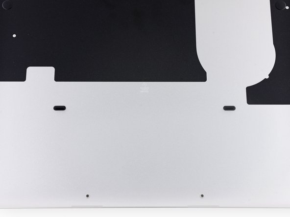
Verwijder de volgende tien schroeven die de onderste behuizing aan de bovenste behuizing bevestigen:
-
Twee 2.3 mm lange P5 Pentalobe schroeven
-
Acht 3.0 mm lange P5 Pentalobe schroeven
-
-
Deze stap is niet vertaald. Help het te vertalen
-
Carefully remove the rubber fan bumper from the edge of the heat sink.
-
-
Deze stap is niet vertaald. Help het te vertalen
-
Use the flat end of a spudger to peel the four foam stickers off of the heat sink screws.
-
-
-
Deze stap is niet vertaald. Help het te vertalen
-
Remove the following screws securing the heat sink to the logic board:
-
Four 2.6 mm T5 screws
-
One 2.4 mm Phillips #000 screw
-
-
Deze stap is niet vertaald. Help het te vertalen
-
Use the tip of a spudger to push on either side of the the iSight camera cable connector to walk it out of its socket on the logic board.
-
-
Deze stap is niet vertaald. Help het te vertalen
-
Peel the iSight camera cable off the fan housing to fold it out of the way.
-
-
Deze stap is niet vertaald. Help het te vertalen
-
Use the tip of a spudger to flip the tab on the fan's ZIF connector.
-
Carefully pull the fan cable straight out of its socket.
-
-
Deze stap is niet vertaald. Help het te vertalen
-
Remove the following screws securing the fan to the upper case:
-
One 5.0 mm T5 Torx screw
-
Two 3.6 mm T5 Torx screws
-
-
Deze stap is niet vertaald. Help het te vertalen
-
Lift the end of the fan closest to the display hinge and remove the fan from the upper case.
-
-
Deze stap is niet vertaald. Help het te vertalen
-
Insert the tip of a spudger under each of the antenna cables near their connectors and pry up to disconnect them from the AirPort board.
-
Connect the long-sleeved cable to the center socket.
-
The short-sleeved cable connects next to the screw.
-
The remaining cable has no sleeve, and connects in the last empty socket, next to the fan.
-
-
Deze stap is niet vertaald. Help het te vertalen
-
Remove the two 2.1 mm T5 Torx screws securing the I/O board cable bracket.
-
Remove the I/O board cable bracket.
-
-
Deze stap is niet vertaald. Help het te vertalen
-
Use the flat end of a spudger to pop the I/O board connector straight up off its socket on the I/O board.
-
Push the I/O board cable up to bend it out of the way.
-
-
Deze stap is niet vertaald. Help het te vertalen
-
Use the tip of a spudger to push on either side of the I/O board connector to walk it out of its socket on the logic board.
-
-
Deze stap is niet vertaald. Help het te vertalen
-
Remove the following screws securing the I/O board to the upper case:
-
One 3.5 mm T8 Torx standoff screw
-
One 3.5 mm T5 Torx screw
-
-
Deze stap is niet vertaald. Help het te vertalen
-
Lift the I/O board cable end of the I/O board and pull toward the logic board to free the ports from the upper case.
-
Remove the I/O board.
-
-
Deze stap is niet vertaald. Help het te vertalen
-
Remove the single 2.7 mm T5 Torx screw securing the AirPort board to the I/O board.
-
-
Deze stap is niet vertaald. Help het te vertalen
-
Lift the free end of the AirPort board up slightly and pull it straight out of its socket on the I/O board.
-
Annuleren: ik heb deze handleiding niet afgemaakt.
15 andere personen hebben deze handleiding voltooid.
4 opmerkingen
very good instructions—easily followed —-thank you so much for this !!!!!
Thank you very much Sam Goldheart! Following your impeccable instruction and armed with Ifixit instruments, I managed to replace the logic board of my MacBook pro without an issue.
Greetings folks, (I have heard of something stupid, but would give it a try.)
Question where is the HDMI Chip on this board located? I have heard from Heise comments that, when you desolder this chip, theoretically, your MacBook Pro retina 2014 mid 13”/Late2013 13” which was bricked due to the Big Sur Upgrade will functioning again.
I would test it in a few months, if there is no other solution besides a replacement board.
Hi, thank you very much for the guides, great helps! So, I’ve just finished swapping what I thought was a faulty IO board and cable out, and it seems like that may have not been the problem as still none of my outputs work on the right side; HDMI, USB, or SD. What do you think could be the potential cause of the problem, if it wasn’t the IO board as I had originally thought? TIA


