Deze versie kan foutieve bewerkingen bevatten. Schakel over naar de recentste gecontroleerde momentopname.
Wat je nodig hebt
-
-
Verwijder de volgende tien schroeven die de onderste behuizing aan de bovenste behuizing bevestigen:
-
Twee 2.3 mm lange P5 Pentalobe-schroeven
-
Acht 3.0 mm lange P5 Pentalobe-schroeven
-
-
-
Verwijder de plastic bescherming die aan het contactbord van de batterij is bevestigd.
-
-
-
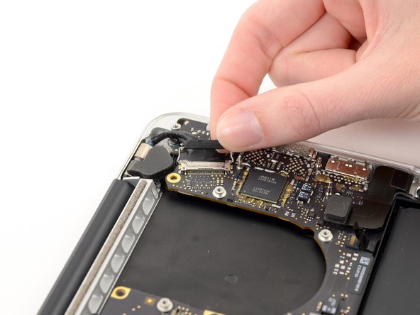
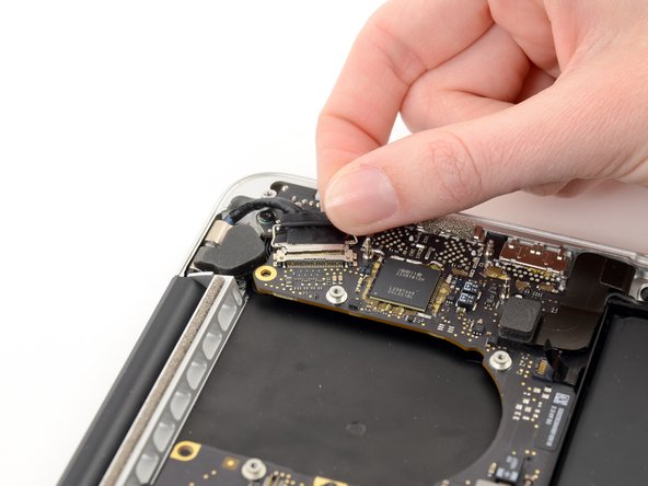
Pak de Interposer met een pincet vast.
-
Til de Interposer van het logic board af en verwijder deze.
-
-
Deze stap is niet vertaald. Help het te vertalen
-
Remove the following screws securing the heat sink to the logic board assembly:
-
One 2.4 mm Phillips #00 screw
-
One 3.4 mm T5 Torx screw
-
Four 2.7 mm T5 Torx screws
-
-
Deze stap is niet vertaald. Help het te vertalen
-
Lift and remove the heat sink up off the logic board assembly.
-
-
Deze stap is niet vertaald. Help het te vertalen
-
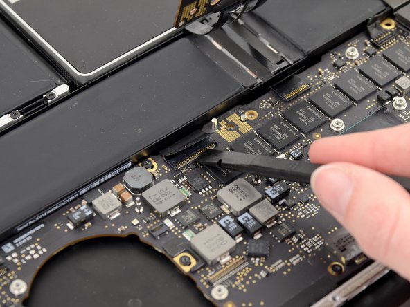
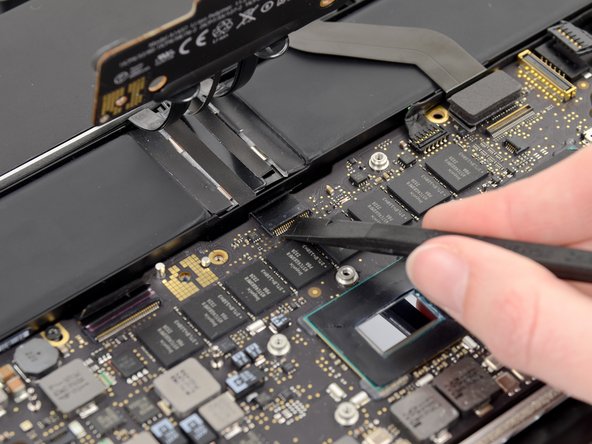
Use the flat end of a spudger to pry the right side of the I/O board data cable connector up off its socket on the I/O board.
-
-
-
Deze stap is niet vertaald. Help het te vertalen
-
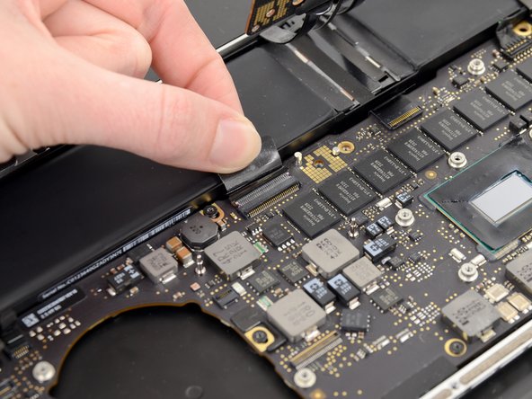
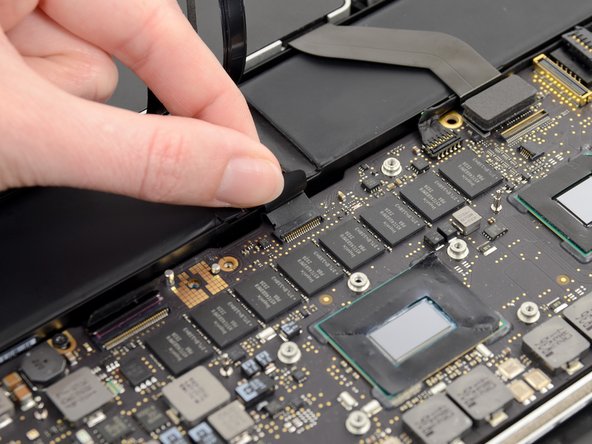
Wedge the flat end of a spudger beneath the left side of the I/O board data cable connector.
-
Gently twist the spudger to disconnect the I/O board data cable connector from its socket on the logic board.
-
-
Deze stap is niet vertaald. Help het te vertalen
-
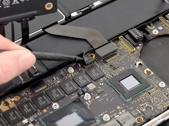
Lift and remove the I/O board data cable from the MacBook Pro.
-
-
Deze stap is niet vertaald. Help het te vertalen
-
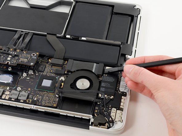
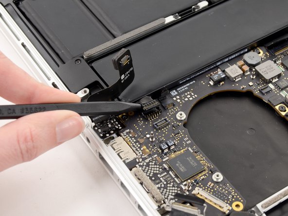
Use the tip of a spudger to flip up the retaining flap on the right fan ribbon cable ZIF socket.
-
Pull the right fan ribbon cable straight out of its socket on the logic board.
-
-
Deze stap is niet vertaald. Help het te vertalen
-
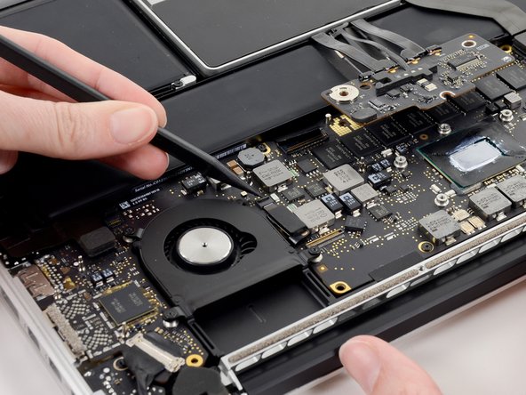
Remove the three 3.1 mm T5 Torx screws securing the right fan to the logic board assembly.
-
-
Deze stap is niet vertaald. Help het te vertalen
-
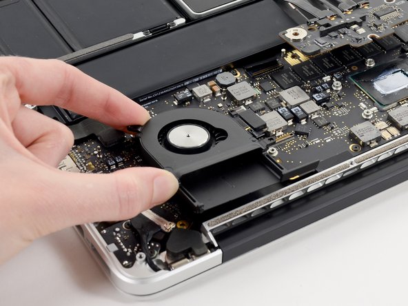
Lift and remove the right fan out of the upper case.
-
-
Deze stap is niet vertaald. Help het te vertalen
-
Use the tip of a spudger to flip up the retaining flap on the left fan ribbon cable ZIF socket.
-
-
Deze stap is niet vertaald. Help het te vertalen
-
Remove the three 3.1 mm T5 Torx screws securing the left fan to the logic board assembly.
-
-
Deze stap is niet vertaald. Help het te vertalen
-
Lift and remove the left fan out of the upper case.
-
-
Deze stap is niet vertaald. Help het te vertalen
-
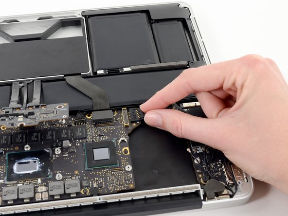
Use the tip of a spudger to push the edges of the I/O board connector straight out of its socket on the logic board.
-
-
Deze stap is niet vertaald. Help het te vertalen
-
Wedge the flat end of a spudger underneath the keyboard backlight connector and the logic board.
-
Gently twist the flat end of a spudger upwards to pry the keyboard backlight connector up off its socket on the logic board.
-
-
Deze stap is niet vertaald. Help het te vertalen
-
Grab the black pull tab secured to the display data cable lock and rotate it toward the DC-In side of the computer.
-
Pull the display data cable straight out of its socket on the logic board.
-
-
Deze stap is niet vertaald. Help het te vertalen
-
Pry the headphone jack cable connector up off its socket on the logic board.
-
-
Deze stap is niet vertaald. Help het te vertalen
-
Use the tip of a spudger to flip up the retaining flap on the microphone ribbon cable ZIF socket.
-
Grasp the plastic pull tab and pull the microphone ribbon cable out of its socket.
-
-
Deze stap is niet vertaald. Help het te vertalen
-
Use the flat edge of a spudger to flip up the retaining flap on the keyboard ribbon cable ZIF socket.
-
Grasp the plastic pull tab and pull the keyboard ribbon cable out of its socket.
-
-
Deze stap is niet vertaald. Help het te vertalen
-
Repeat the previous procedure to disconnect the Trackpad ribbon cable from its socket on the logic board.
-
-
Deze stap is niet vertaald. Help het te vertalen
-
Wedge the flat end of a spudger beneath the right speaker cable connector.
-
Gently pry the right speaker cable connector up off from its socket on the logic board.
-
-
Deze stap is niet vertaald. Help het te vertalen
-
Use the flat end of a spudger to pry the SSD cable connector up off its socket on the logic board.
-
-
Deze stap is niet vertaald. Help het te vertalen
-
Wedge the tip of a spudger beneath the left speaker cable connector.
-
Gently pry the left speaker cable connector up off from its socket on the logic board.
-
-
Deze stap is niet vertaald. Help het te vertalen
-
Remove the nine 3.3 mm T5 Torx screws securing the logic board and MagSafe DC-in board to the upper case.
-
-
Deze stap is niet vertaald. Help het te vertalen
-
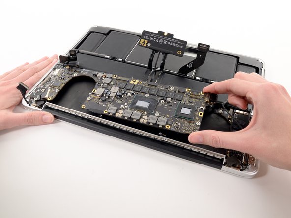
Carefully grasp the corner of the logic board (opposite of the I/O ports) and lift the logic board out of the upper case.
-
-
Deze stap is niet vertaald. Help het te vertalen
-
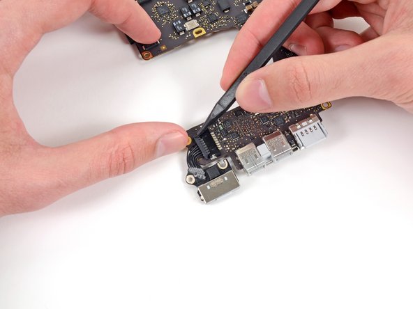
Gently push the edges of the MagSafe cable connector away from its socket on the logic board.
-
-
Deze stap is niet vertaald. Help het te vertalen
-
Pull the MagSafe cable connector straight out of its socket on the logic board.
-


Annuleren: ik heb deze handleiding niet afgemaakt.
14 andere personen hebben deze handleiding voltooid.

Één opmerking
Great tutorial. I would add two comments. Firstly between steps 14 and 15 there is a cable that needs to be unconnected (see other tutorials where it is detailed) - it needs to be "walked" out, and you ned to remember to reconnect this. Secondly when putting the logic board back in be sure not to trap any of the connectors underneath it. It is a real struggle! I ended up undoing the 6 screws that hold the main battery assembly in and lifting this slightly to give me space and allow me to reinsert the ribbon cables on that side of the board. The reason I needed to disassemble my laptop was that it kept going into sleep mode, sometimes every few seconds. Apple wanted to charge £550 to fix it. I found the problem was with the micro-switch that detects if the lid is closed (it would work fine in clamshell mode). Switch is between the thunder port and USB sockets. Sprayed with contact cleaner, isopropyl and antistatic spray and dried with hairdryer, been working a treat since! Cost of a pentalobe driver!