Ga door naar hoofdinhoud

Deze handleiding heeft recentere wijzigingen. Schakel over naar de nieuwste niet-geverifieerde versie.

Logic Board Connectors

Alleen vereisten
Deze handleiding is alleen bedoeld als vereiste voor andere handleidingen. Het staat niet op zichzelf.

Wat je nodig hebt

  1. Logic Board Connectors, Disconnect the logic board: stap 1, afbeelding 1 van 2 Logic Board Connectors, Disconnect the logic board: stap 1, afbeelding 2 van 2
    • Use the flat end of a spudger to disconnect the camera cable connector by prying it straight up from its socket.

  2. Logic Board Connectors: stap 2, afbeelding 1 van 1
    Gereedschap gebruikt in deze stap:
    Standoff Screwdriver for iPhones
    $5.49
    Koop
    • Remove the two screws securing the rear-facing camera bracket:

    • One 3.0 mm standoff screw

    • One 3.1 mm Phillips screw

    • Standoff screws are best removed using a standoff screwdriver or bit.

    • In a pinch, a small flathead screwdriver will do the job—but use extra caution to ensure it doesn't slip and damage surrounding components.

  3. Logic Board Connectors: stap 3, afbeelding 1 van 1
    • Remove the rear-facing camera bracket.

  4. Logic Board Connectors: stap 4, afbeelding 1 van 2 Logic Board Connectors: stap 4, afbeelding 2 van 2
    • Use the point of a spudger to disconnect the flash connector from its socket by prying it straight up.

  5. Logic Board Connectors: stap 5, afbeelding 1 van 1
    • Remove the two screws securing the upper cable bracket:

    • One 2.9 mm Phillips screw

    • One 1.3 mm Phillips screw

  6. Logic Board Connectors: stap 6, afbeelding 1 van 1
    • Remove the upper cable bracket.

  7. Logic Board Connectors: stap 7, afbeelding 1 van 2 Logic Board Connectors: stap 7, afbeelding 2 van 2
    • Use the flat end of a spudger to pry the upper cable connector up from its socket.

  8. Logic Board Connectors, Remove the top left antenna component: stap 8, afbeelding 1 van 1
    • Remove the three Phillips 1.3 mm screws securing the top left antenna component.

  9. Logic Board Connectors: stap 9, afbeelding 1 van 1
    • Remove the 1.4 mm Phillips screw securing the antenna component to the top of edge of the case.

  10. Logic Board Connectors: stap 10, afbeelding 1 van 1
    • Remove the antenna component.

  11. Logic Board Connectors, Remove the top left grounding clip: stap 11, afbeelding 1 van 1
    • Remove the two Phillips screws securing the grounding clip at the top left edge of the logic board:

    • One 1.5 mm Phillips screw

    • One 2.6 mm Phillips screw

  12. Logic Board Connectors: stap 12, afbeelding 1 van 1
    • Remove the grounding clip.

  13. Logic Board Connectors, Unscrew the logic board: stap 13, afbeelding 1 van 1
    • Remove the three screws securing the motherboard:

    • One 1.8 mm Phillips screw

    • One 2.5 mm standoff screw

    • One 2.2 mm standoff screw

  14. Logic Board Connectors: stap 14, afbeelding 1 van 2 Logic Board Connectors: stap 14, afbeelding 2 van 2
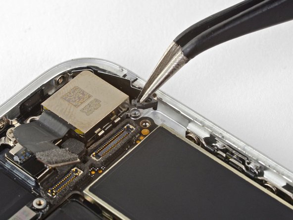
    • Use tweezers to gently bend the logic board grounding bracket out of the way.

  15. Logic Board Connectors: stap 15, afbeelding 1 van 2 Logic Board Connectors: stap 15, afbeelding 2 van 2
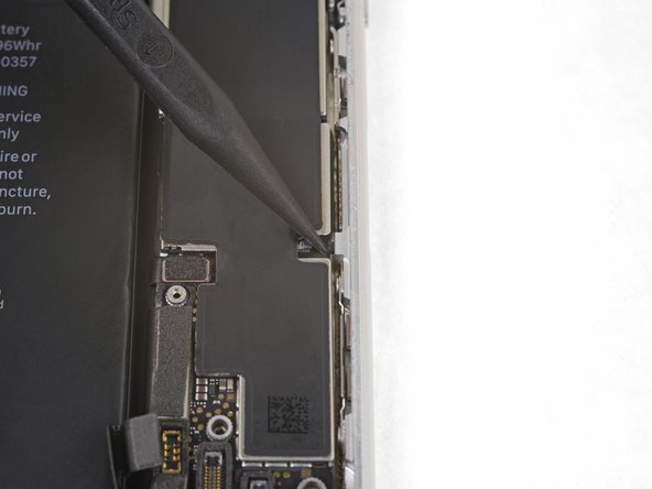
    • Use the point of a spudger to move the SIM card eject plunger out of the logic board's way.

Conclusie

To reassemble your device, follow the above steps in reverse order.

Take your e-waste to an R2 or e-Stewards certified recycler.

Repair didn’t go as planned? Check out our Answers community for troubleshooting help.

Arthur Shi

Lid sinds: 01/03/18

249.815 Reputatie

503 handleidingen geschreven

Team

iFixit Lid van iFixit

Staff

135 Leden

16.731 handleidingen geschreven

0 opmerkingen

Voeg opmerking toe

Weergavestatistieken:

Afgelopen 24 uren: 0

Afgelopen 7 dagen: 1

Afgelopen 30 dagen: 1

Altijd: 207