Deze versie kan foutieve bewerkingen bevatten. Schakel over naar de recentste gecontroleerde momentopname.
Wat je nodig hebt
-
Deze stap is niet vertaald. Help het te vertalen
-
Slide the orange latch sideways to eject the battery.
-
Remove the battery from the battery slot.
-
-
Deze stap is niet vertaald. Help het te vertalen
-
Using a Phillips #00 screwdriver, remove two 5.39 mm screws next to the battery slot.
-
Remove the metal piece holding down the lanyard, then remove the lanyard.
-
-
Deze stap is niet vertaald. Help het te vertalen
-
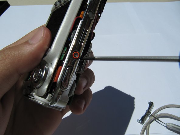
Using a Phillips #00 screwdriver, remove seven screws located on the outside case of the camera.
-
One 6.25 mm screw is located on the top right corner, right to the "OK" button.
-
Four 4.45 mm screws are on the bottom of the camera.
-
Two 2.95 mm screws are on the left side of the camera, above the USB port.
-
-
Deze stap is niet vertaald. Help het te vertalen
-
Carefully remove the rear camera casing.
-
Carefully remove the front camera casing.
-
-
-
Deze stap is niet vertaald. Help het te vertalen
-
Remove the back panel screws (1x 3.33mm, and 1x 3.40mm).
-
-
Deze stap is niet vertaald. Help het te vertalen
-
Gently pull the orange tab out of the circuit board.
-
-
Deze stap is niet vertaald. Help het te vertalen
-
Remove the (1x 3.33mm) screw from the menu button panel .
-
-
Deze stap is niet vertaald. Help het te vertalen
-
Pull the second orange tab from the circuit board and remove the buttons.
-
-
Deze stap is niet vertaald. Help het te vertalen
-
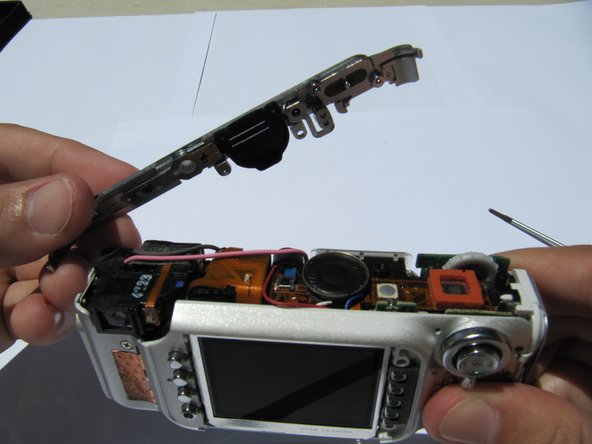
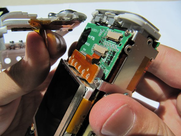
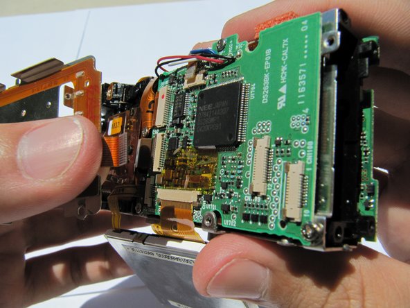
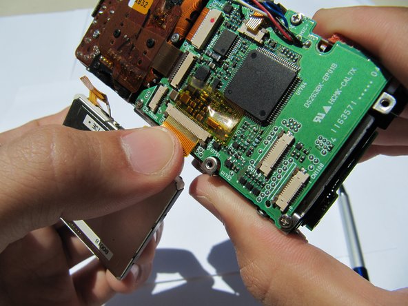
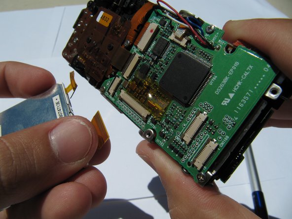
Flip up the LCD screen to reveal the two orange ribbon cables.
-
Disconnect the two ribbons cables from their sockets on the motherboard.
-
-
Deze stap is niet vertaald. Help het te vertalen
-
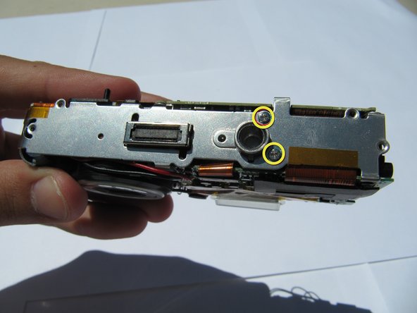
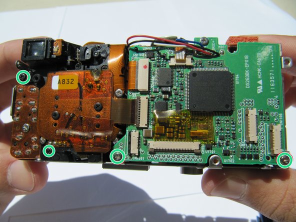
Connect the two capacitor wires briefly with a pair of metal tweezers to discharge the capacitor. You may see a small spark.
-
Remove eight screws using a Phillips #00 screwdriver.
-
Two (4.31 mm) screws are in the front of the camera.
-
Two (3.30 mm) screws are located in the bottom of the camera.
-
Four (3 x 3.33 mm and 1 x 4.34 mm) screws are in the back of the camera.
-
-
Deze stap is niet vertaald. Help het te vertalen
-
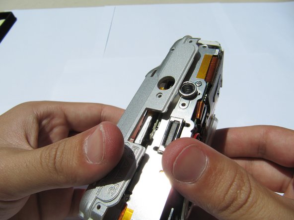
Remove the tripod mount from the bottom of the camera and set it aside.
-
-
Deze stap is niet vertaald. Help het te vertalen
-
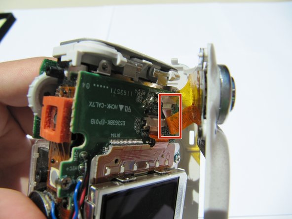
Pull the black latch outward slightly to release the orange flex cable.
-
Carefully disconnect the orange flex cable.
-
-
Deze stap is niet vertaald. Help het te vertalen
-
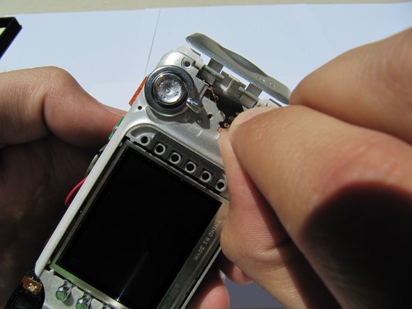
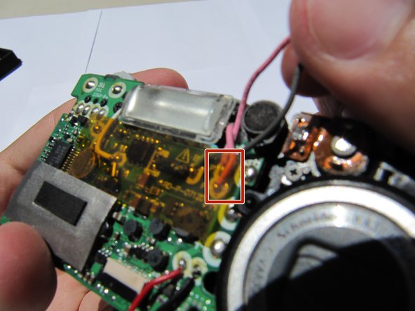
Hold the camera firmly and gently remove the capacitor (attached by adhesive) by wiggling it loose.
-
Desolder the pink and black wire and remove both of them.
-
-
Deze stap is niet vertaald. Help het te vertalen
-
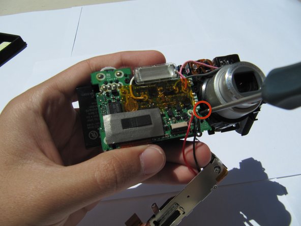
Remove the (1x4.27) screw from the front of the camera.
-
-
Deze stap is niet vertaald. Help het te vertalen
-
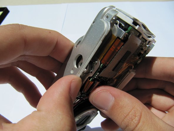
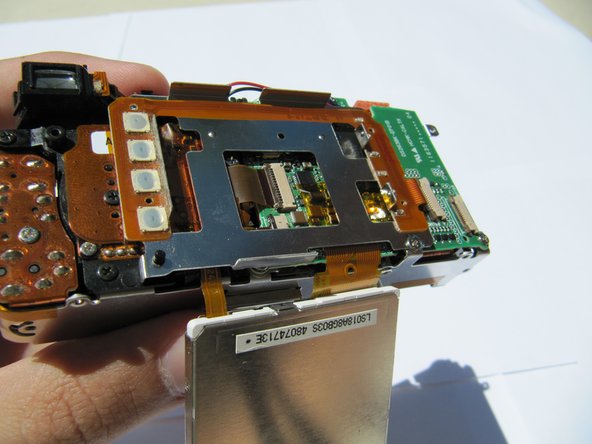
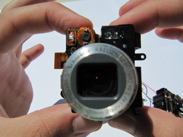
Remove the orange tabs from the back of the camera to remove the lens.
-


Annuleren: ik heb deze handleiding niet afgemaakt.
Één andere persoon heeft deze handleiding voltooid.
Team

Cal Poly, Team 2-8, Johann Summer 2010 Lid van Cal Poly, Team 2-8, Johann Summer 2010
CPSU-JOHANN-R10S2G8
5 Leden
16 handleidingen geschreven