Deze versie kan foutieve bewerkingen bevatten. Schakel over naar de recentste gecontroleerde momentopname.
Wat je nodig hebt
-
Deze stap is niet vertaald. Help het te vertalen
-
Place the device face down on a clean cloth or another smooth surface.
-
Insert the plastic opening tool between the device’s front and back panels. You might need to wiggle the tool up and down to wedge it in the gap.
-
Maneuver the tool around the device until the back unclips from the front panel.
-
-
Deze stap is niet vertaald. Help het te vertalen
-
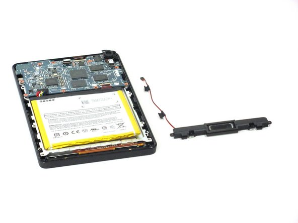
Carefully separate the back panel from the rest of the device internals.
-
-
Deze stap is niet vertaald. Help het te vertalen
-
Unscrew the two 3.5mm T5 Torx screws at the base of the speaker.
-
-
Deze stap is niet vertaald. Help het te vertalen
-
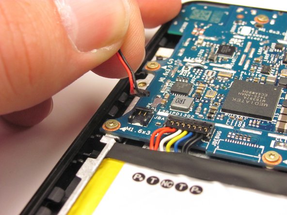
Unclip the speaker wire that runs up the side of the battery and clips into the motherboard next to the battery connector. Gently pull it straight up.
-
-
Deze stap is niet vertaald. Help het te vertalen
-
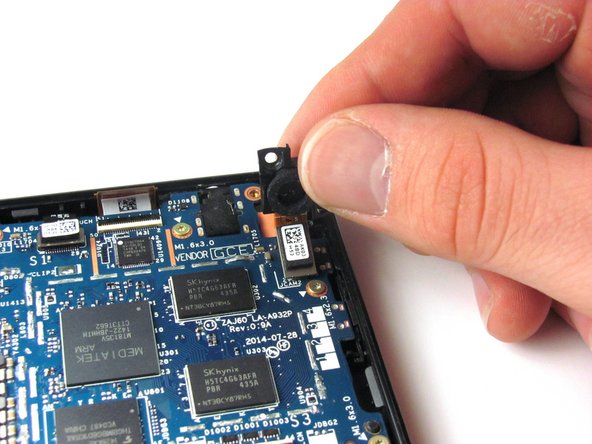
Unscrew the two 3.5mm T5 Torx Screws from the top of the camera.
-
-
Deze stap is niet vertaald. Help het te vertalen
-
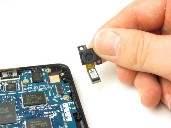
Gently pull the camera up and out of the device. As you pull, unclip the black and white connector with orange tape by popping it off at its base.
-
-
-
Deze stap is niet vertaald. Help het te vertalen
-
Gently pry the battery free from the adhesive holding it in place.
-
If you're having trouble working the battery free, warm it up with an iOpener or hair dryer to soften the adhesive, and then slide a credit card behind the battery to break up the adhesive.
-
-
Deze stap is niet vertaald. Help het te vertalen
-
Remove the multi-colored connector that joins the battery and the motherboard by pulling it straight up.
-
Remove the battery.
-
-
Deze stap is niet vertaald. Help het te vertalen
-
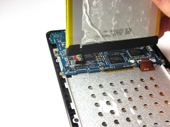
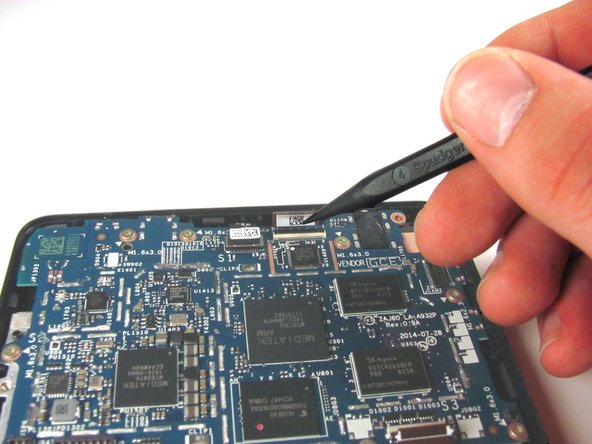
Use the tip of the spudger to disconnect the two zero insertion force connectors on the bottom and top of the motherboard.
-
The first connector is attached to an orange tape, and is located in the bottom-right corner of the motherboard. Remove this connector.
-
The second connector is long and thin, and is located at the top of the motherboard, a bit to the right of center. Remove this connector.
-
-
Deze stap is niet vertaald. Help het te vertalen
-
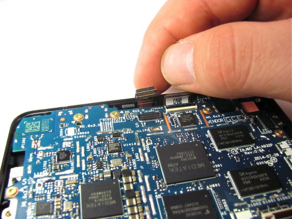
Disconnect the black and white connector at the very top-center of the motherboard by unclipping it using the flat side of the spudger.
-
-
Deze stap is niet vertaald. Help het te vertalen
-
Unscrew the ten 3.5mm T5 Torx screws around the edge of the motherboard.
-
-
Deze stap is niet vertaald. Help het te vertalen
-
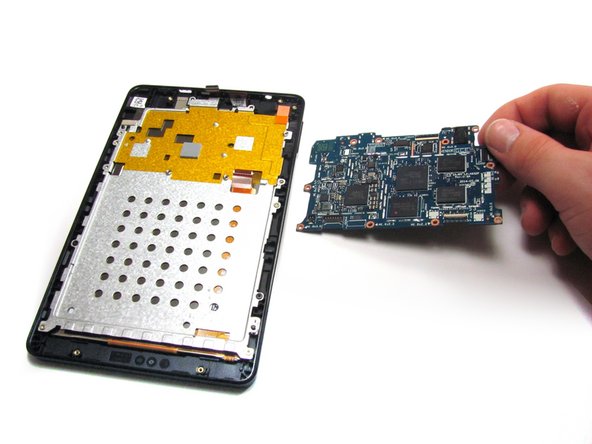
Starting from the bottom, lift the motherboard out of the device. You will have to push the motherboard about two millimeters toward the top of the device to unhook the top edge.
-
-
Deze stap is niet vertaald. Help het te vertalen
-
Remove the five gold-colored 2mm T5 Torx screws from the metal plate.
-
-
Deze stap is niet vertaald. Help het te vertalen
-
Lift the metal plate up using the flat side of the spudger.
-
-
Deze stap is niet vertaald. Help het te vertalen
-
Unscrew the four silver-colored 2mm T5 Torx screws that connect the screen to the bezel.
-
-
Deze stap is niet vertaald. Help het te vertalen
-
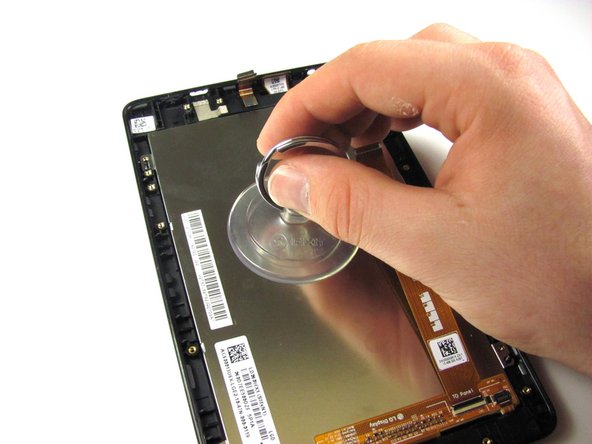
Push the suction cup against the screen. Press down firmly on the center of the suction cup to create a good seal.
-
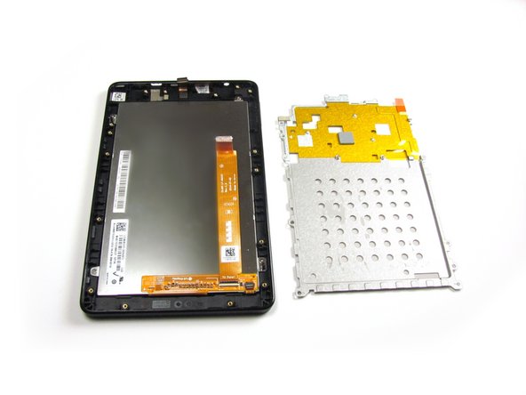
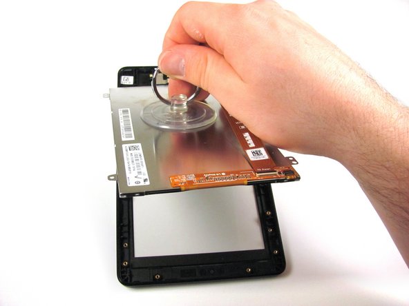
Gently pull the screen out of the device.
-
-
Deze stap is niet vertaald. Help het te vertalen
-
Place your screen on a cloth or another smooth surface to prevent it from getting scratched.
-


Annuleren: ik heb deze handleiding niet afgemaakt.
11 andere personen hebben deze handleiding voltooid.
Team

Cal Poly, Team 70-4, Forte Winter 2015 Lid van Cal Poly, Team 70-4, Forte Winter 2015
CPSU-FORTE-W15S70G4
4 Leden
12 handleidingen geschreven
8 opmerkingen
Yes, author didn't go the complete distance. When actually removing glass by heating til adhesive softens. And releases from the bezel. Before tossing the cracked digitizer, I noticed 2 silver rectangle pieces, stuck to outer glass adhesive. That had black double stick tape on these pieces of silver colored metal which are a smaller rectangle. And somewhat camouflaged their existence . And I determined, they stick to rectangle recesses in the bezel. Easily overlooked by most. I hunted around, never finding any reference anywhere in text or video. However, I did find a picture of them. On a pink colored bezel on ebay. I don't know their function, but, could it the source of the problem that people are experiencing. After they replace digitizer they can't get the fire hd 6 to recognize it. DON'T KNOW! Hope you can shed some light on this!!! Other than this snafu, I give author good marks for the rest of very helpful guides Thank you.
I just did this, twice actually. The first time I tried to separate the new digitizer from the frame, since the replacement frame was black and my original was blue. BAD IDEA. Don't do it - trying to get it out of the frame, settled into the original one, including the metal spacers referred to above, is bound to fail. Just remove the camera from the old frame with the cracked digitizer and move it to the new one - it's only taped in place. Other than that and the fact that the article *seriously* understates the incredible amount of 2-sided glued foam that holds the battery in, the replacement was a breeze.
Add me to the list of people who tried this but ended up with a non-working digitizer after replacement. Anyone ever figure this out?