Deze versie kan foutieve bewerkingen bevatten. Schakel over naar de recentste gecontroleerde momentopname.
Wat je nodig hebt
-
Deze stap is niet vertaald. Help het te vertalen
-
Remove both end caps by putting a plastic opening tool in the center of the seam. Work around the edges to pry the end caps off completely.
-
-
Deze stap is niet vertaald. Help het te vertalen
-
Turn the Jambox upside down. Peel the indicated rubber tabs off, using a plastic opening tool if necessary.
-
Remove the three T6, 7.0 mm screws under each rubber tab.
-
-
Deze stap is niet vertaald. Help het te vertalen
-
With the Jawbone logo facing towards you and with correct orientation, place the Jambox with the left end cap facing upward.
-
Unscrew indicated T6 9.7 mm screws.
-
Gently loosen the tabs from their anchor points so the bottom may be removed.
-
Flip the Jambox so the other end cap is facing up. The USB cable is on this side (metal grounding clip, indicated in orange). Repeat the above two steps.
-
-
Deze stap is niet vertaald. Help het te vertalen
-
Pry up the bottom panel by lifting from the device.
-
Pull the bottom up. This may take a bit of force as the bottom is glued to device.
-
Once removed, the battery will now be visible.
-
-
Deze stap is niet vertaald. Help het te vertalen
-
Unscrew the eight indicated T6 9.8 mm screws. Remove metal grounding plates.
-
-
-
Deze stap is niet vertaald. Help het te vertalen
-
Once all eight screws are removed, pry the sides of the Jambox to lift the body from it's shell.
-
-
Deze stap is niet vertaald. Help het te vertalen
-
With the battery facing forward, remove the three indicated T6 9.5 mm screws.
-
Once the screws are removed, lift up the small plastic plate, revealing the auxiliary board underneath.
-
-
Deze stap is niet vertaald. Help het te vertalen
-
Turn the Jambox so that the button panel is visible.
-
Remove the indicated screws, T6 9.6 mm.
-
-
Deze stap is niet vertaald. Help het te vertalen
-
Remove the colored ribbon that connects the green button circuit board to the blue auxiliary board by using your finger to lift the small black tabs that clamp down the ribbon.
-
-
Deze stap is niet vertaald. Help het te vertalen
-
Remove the indicated T6 7.4 mm screw holding the auxiliary board in place.
-
Carefully lift the auxiliary board up and off to the side.
-
-
Deze stap is niet vertaald. Help het te vertalen
-
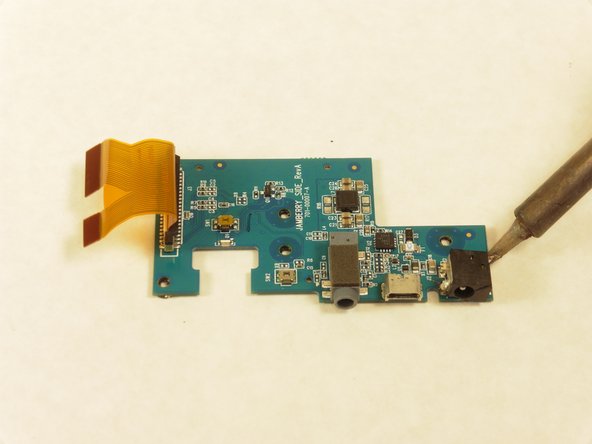
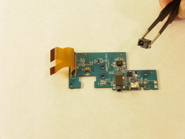
With the auxiliary board removed, use a soldering iron to heat the metal keeping the charge port (indicated on image) intact.
-
Remove the charge port from the auxiliary board.
-
-
Deze stap is niet vertaald. Help het te vertalen
-
The new charge port will need to be soldered to the logic board. For an exact match use Digi-Key part number CP-018HPJCT-ND
-
-
Deze stap is niet vertaald. Help het te vertalen
-
With a multimeter, test all 3 PCB contacts to determine which are positive, negative and ground. Similarly, ascertain each terminal of your "new" charger port and its corresponding PCB contact. Your "new" port can be a brand-new, identical replacement or a salvaged one of approximate size, post thickness and terminal orientation.
-
Unless an identical part replacement, you may have to bend your ports terminals in order to make proper contact and'or enlarge the panel opening for the AC plug as I did. To avoid repeat part failure, I hot-glued my charger port onto my PCB after reinforcing my port's terminals with thicker wire and generous solder.
-


Annuleren: ik heb deze handleiding niet afgemaakt.
21 andere personen hebben deze handleiding voltooid.
Team

Cal Poly, Team 24-5, Lancaster Spring 2015 Lid van Cal Poly, Team 24-5, Lancaster Spring 2015
CPSU-LANCASTER-S15S24G5
4 Leden
9 handleidingen geschreven
11 opmerkingen
Good instruction!
Problem is that the C14 got snapped off too! Not sure if it is really needed. Possible to get the complete board?
I lost C14 as well, anyone have a good replacement number for that?
Jason -
FYI the device will charge and power on without this capacitor. Not sure if it is needed for USB or 3.5mm output, but I don't really care about either of those scenarios.
Jason -