Ga door naar hoofdinhoud

HP TouchPad USB Connector Board Replacement

Wat je nodig hebt

  1. HP TouchPad USB Connector Board Replacement, Front Panel Assembly: stap 1, afbeelding 1 van 1
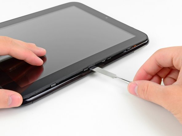
    • In the following steps, you will use a metal spudger to lift the front panel out from the rear case of your TouchPad.

    • The front panel is held in by seven clips (boxed in red) that are lightly anchored to the rear case. When you remove the front panel assembly, you are bound to break either the clips or their supports attached to the rear case. We will update this guide as we find replacement parts or a better method to remove the panel.

    • As you remove the front panel assembly, also be careful not to damage the ambient light sensor (boxed in yellow) or the two antennas (boxed in orange).

  2. HP TouchPad USB Connector Board Replacement: stap 2, afbeelding 1 van 1
    • Insert a flat metal spudger in the gap between the rubber outer ring on the front panel assembly and the black plastic rear case near the USB connector.

    • Pry the front panel assembly up from the rear case, being careful not to damage the LCD or the glass panel.

    • As you work through the following steps, insert your metal spudger and pry the front panel up, but do not try to slide the spudger along the gap you're creating. Always remove your spudger, then insert it at another spot and pry upward.

  3. HP TouchPad USB Connector Board Replacement: stap 3, afbeelding 1 van 2 HP TouchPad USB Connector Board Replacement: stap 3, afbeelding 2 van 2
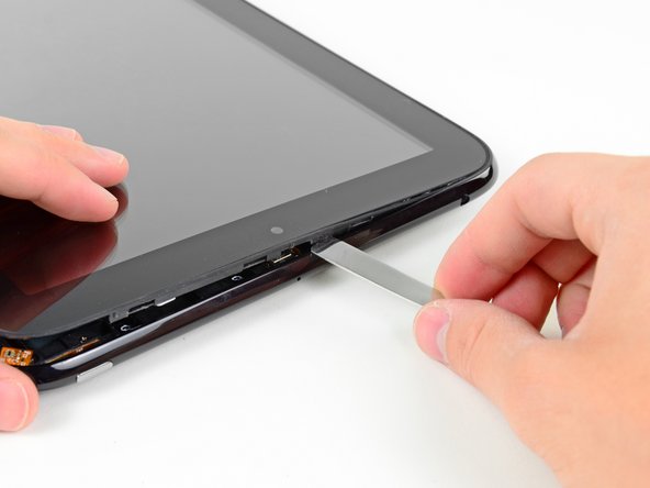
    • As in the previous step, use a spudger to pry the front panel up from the rear case along its long edge on the volume button side of the TouchPad.

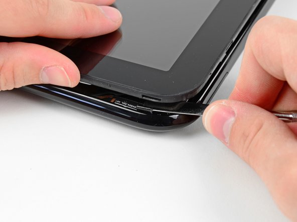
    • Continue to pry the front panel assembly up along the volume button side of the TouchPad until there is a gap between it and the rear case.

  4. HP TouchPad USB Connector Board Replacement: stap 4, afbeelding 1 van 2 HP TouchPad USB Connector Board Replacement: stap 4, afbeelding 2 van 2
    • Pry up the front panel assembly along the top edge of the TouchPad.

    • Be careful not to damage the ambient light sensor or the upper antenna.

  5. HP TouchPad USB Connector Board Replacement: stap 5, afbeelding 1 van 1
    • Pry up the front panel along the edge closest to the home screen button.

  6. HP TouchPad USB Connector Board Replacement: stap 6, afbeelding 1 van 2 HP TouchPad USB Connector Board Replacement: stap 6, afbeelding 2 van 2
    • Before lifting the free side of the front panel up from the rear case, you may need to release it from the plastic retaining clips holding it down.

    • Use your metal spudger to pull the stuck retaining clips away from the edge of the front panel.

  7. HP TouchPad USB Connector Board Replacement: stap 7, afbeelding 1 van 1
    • After freeing the retaining clips, lift the front panel assembly away from the rear case.

    • Do not try to remove the front panel assembly from the TouchPad just yet, as it is still connected to the motherboard.

  8. HP TouchPad USB Connector Board Replacement: stap 8, afbeelding 1 van 1
    • Use the attached black tab to pull the display data cable straight up and out of its socket on the motherboard.

    • Pull the cable upwards and not parallel to the face of the motherboard. Doing otherwise may damage the socket on the motherboard.

    • Take care not to pull on the ribbon that is stuck by adhesive to the bottom of cable you are detaching. It does not need to be disconnected.

  9. HP TouchPad USB Connector Board Replacement: stap 9, afbeelding 1 van 3 HP TouchPad USB Connector Board Replacement: stap 9, afbeelding 2 van 3 HP TouchPad USB Connector Board Replacement: stap 9, afbeelding 3 van 3
    • Use your fingernail to carefully flip up the retaining flaps on the two digitizer ribbon cable ZIF sockets.

    • Be sure you are prying up on the hinged retaining flaps, not the sockets themselves.

    • Pull the digitizer ribbon cable straight out of its two sockets on the motherboard.

  10. HP TouchPad USB Connector Board Replacement: stap 10, afbeelding 1 van 1
    • Remove the front panel assembly from the rear case assembly.

  11. HP TouchPad USB Connector Board Replacement, USB Connector Board: stap 11, afbeelding 1 van 2 HP TouchPad USB Connector Board Replacement, USB Connector Board: stap 11, afbeelding 2 van 2
    • Use the edge of a plastic opening tool to peel up the two pieces of copper tape covering the USB connector board near the battery and the motherboard.

  12. HP TouchPad USB Connector Board Replacement: stap 12, afbeelding 1 van 1
    • Remove the four 3.2 mm Phillips screws securing the USB connector board to the rear case.

  13. HP TouchPad USB Connector Board Replacement: stap 13, afbeelding 1 van 1
    • Pry the upper end of the USB connector board upwards to disconnect it from its socket on the logic board.

  14. HP TouchPad USB Connector Board Replacement: stap 14, afbeelding 1 van 1
    • Pull the USB connector board away from the bottom edge of the rear case and lift, but do not remove it out of its housing.

    • The USB connector board is still attached to the vibrator motor. Do not completely remove the USB connector board just yet.

  15. HP TouchPad USB Connector Board Replacement: stap 15, afbeelding 1 van 3 HP TouchPad USB Connector Board Replacement: stap 15, afbeelding 2 van 3 HP TouchPad USB Connector Board Replacement: stap 15, afbeelding 3 van 3
    • Pull the vibrator motor connector straight away from its socket on the USB connector board.

    • Remove the USB connector board from the TouchPad.

    • NOTE: First verify that there is a connector before pulling! The vibrator motor may be soldered directly to the USB Board requiring the motor to be pried up and removed together with the board.

Conclusie

To reassemble your device, follow these instructions in reverse order.

13 andere personen hebben deze handleiding voltooid.

4 opmerkingen

I took my Touchpad apart to fix a problem with the USB connector. It is worth mentioning that it is possible to remove the front panel without breaking any clips or causing any damage. You will just need to use a second spudger to "release" the connectors from the front panel, instead of just prying the panel up like the guide says. (Wish I could give more detail, but my edits to the panel guide didn't make the cut. Maybe one of the Ifixit mods could explain it better.)

JBS - Antwoord

(quote) It is worth mentioning that it is possible to remove the front panel without breaking any clips or causing any damage. You will just need to use a second spudger to "release" the connectors from the front panel, instead of just prying the panel up like the guide says.(Un-Quote)

I also have tried this, what you do is use one tool to pry open the side so you can see a gap and the clips. Then with a second tool you un-clip the clips from the screen by putting a the second tool between the clips and the screen releasing it without any damage. They are a clip attached to the back case and the plastic acts like a sprig to keep the clips attached to the screen panel.

Thank You

Adam - Antwoord

Step 9 says, "Use your fingernail to carefully flip up the retaining flaps on the two digitizer ribbon cable ZIF sockets." That's what I did, but I found it impossible to reconnect the ribbon cables until I took out the board the sockets are on. Even then it was very difficult to reattach the ribbon cables. I recommend leaving them in place and removing the board - which is only held by two screws and a small ribbon connector.

Francis Banks - Antwoord

Where could I buy one of those usb charger dock?

Darian - Antwoord

Voeg opmerking toe

Weergavestatistieken:

Afgelopen 24 uren: 0

Afgelopen 7 dagen: 1

Afgelopen 30 dagen: 8

Altijd: 28,606