Ga door naar hoofdinhoud

Deze versie kan foutieve bewerkingen bevatten. Schakel over naar de recentste gecontroleerde momentopname.

Wat je nodig hebt

  1. , Achterste behuizing: stap 1, afbeelding 1 van 1
    • Verwarm een iOpener en leg deze gedurende ongeveer een minuut op de onderkant van de telefoon.

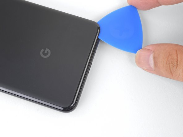
    • Zorg dat je je plectrum, bij het wrikken boven de aan-/uitknop, niet te ver in het toestel steekt. Als je dit wel doet, riskeer je de kabel van de vingerafdruksensor te beschadigen.

  2. : stap 2, afbeelding 1 van 3 : stap 2, afbeelding 2 van 3 : stap 2, afbeelding 3 van 3
    • Druk een zuignap op de verwarmde onderkant van de glazen achterkant.

    • Zorg dat je je zuignap niet per ongeluk op het scherm drukt.

    • Als je glazen achterkant gebarsten is, kun je deze beplakken met wat doorzichtige tape zodat de zuignap zich vast kan zuigen.

    • Trek de zuignap met een sterke, constante kracht omhoog om zo een kleine opening te creëren.

    • Afhankelijk van de leeftijd van je telefoon kan dit aardig wat kracht vereisen. Als je moeite hebt met het creëren van een opening gebruik je wat meer warmte en probeer je het nog eens.

    • Steek een openingsplectrum in de opening.

  3. Deze stap is niet vertaald. Help het te vertalen

    : stap 3, afbeelding 1 van 1
    • When inserting an opening pick above the power button, be careful not to insert the pick too deeply, or you will damage the fingerprint sensor cable.

  4. : stap 4, afbeelding 1 van 3 : stap 4, afbeelding 2 van 3 : stap 4, afbeelding 3 van 3
    • Snijd de lijm langs de onderkant van het toestel door en schuif je plectrum rondom de rechter onderhoek verder.

    • Laat je plectrum in de onderkant zitten om te voorkomen dat de lijm zich opnieuw gaat hechten.

  5. : stap 5, afbeelding 1 van 3 : stap 5, afbeelding 2 van 3 : stap 5, afbeelding 3 van 3
    • Verwarm de rechterzijde van het toestel met een iOpener en ga verder met het doorsnijden van de lijm met behulp van je plectrum.

    • De lijm kan erg plakkerig zijn. Het kan helpen om je plectrum in een zagende beweging heen en weer te trekken om de lijm door te kunnen snijden.

  6. : stap 6, afbeelding 1 van 3 : stap 6, afbeelding 2 van 3 : stap 6, afbeelding 3 van 3
    • Ga verder met het verwarmen en doorsnijden van de lijm rondom de gehele buitenkant van de telefoon. Laat een plectrum in iedere hoek zitten om te voorkomen dat de lijm zich opnieuw gaat hechten.

    • Zorg dat je je plectrum, bij het doorsnijden van de lijm boven de aan-/uitknop, niet te diep in het toestel steekt. Als je dit wel doet, riskeer je de kabel van de vingerafdruksensor te beschadigen.

  7. : stap 7, afbeelding 1 van 3 : stap 7, afbeelding 2 van 3 : stap 7, afbeelding 3 van 3
    • Als je de lijm langs de gehele buitenkant van de telefoon hebt door weten te snijden, kun je de linkerzijde van de glazen achterkant op voorzichtige wijze optillen.

    • Probeer de achterste behuizing nog niet volledig te verwijderen, aangezien deze nog steeds aan de telefoon bevestigd is door middel van de kabel van de vingerafdruksensor.

    • Klap de achterste behuizing via de zijkant open en laat deze zodanig op een object rusten dat de kabel van de vingerafdruksensor niet onnodig onder spanning wordt gezet.

  8. : stap 8, afbeelding 1 van 1
    • Verwijder de twee 4.1 mm lange Phillips-schroeven die de beugel op de aansluiting van de vingerafdruksensor bevestigen.

    • Ga bij het weer in elkaar zetten van je toestel voorzichtig te werk en zorg dat je deze schroeven niet te strak aandraait. Als je dit wel doet, riskeer je je scherm te beschadigen.

  9. : stap 9, afbeelding 1 van 3 : stap 9, afbeelding 2 van 3 : stap 9, afbeelding 3 van 3
    • Gebruik de punt van je spudger om de beugel op de aansluiting van de vingerafdruksensor onder de NFC-spoel vandaan te schuiven.

    • Verwijder de beugel op de aansluiting van de vingerafdruksensor.

  10. : stap 10, afbeelding 1 van 2 : stap 10, afbeelding 2 van 2
    • Gebruik de punt van een spudger om de aansluiting van de vingerafdruksensor uit het contact omhoog te wrikken en los te koppelen.

    • Wees bij het loskoppelen van dit soort aansluitingen voorzichtig en voorkom dat je de om het contact liggende onderdelen mee omhoog wrikt.

    • Om drukaansluitingen als deze weer aan te sluiten, breng je de aansluiting op de juiste positie boven het contact en druk je eerst de ene en dan de andere kant van de aansluiting naar beneden. Druk niet op het midden, aangezien je de pinnen daarmee kunt verbuigen als de aansluiting niet goed geplaatst is.

  11. : stap 11, afbeelding 1 van 3 : stap 11, afbeelding 2 van 3 : stap 11, afbeelding 3 van 3
    • Verwijder de achterste behuizing.

    • Zorg dat je all lijmresten uit het frame van de telefoon verwijdert alvorens je de nieuwe achterste behuizing installeert. Gebruik een openingstool en wat isopropyl alcohol om het oppervlak schoon te maken.

    • Zorg dat je, als je de achterste behuizing hergebruikt, alle lijmresten eerst verwijdert en daarna nieuwe kleefstrips of tape aanbrengt om je oude behuizing te bevestigen.

    • Vergelijk je nieuwe achterkant, voordat je deze bevestigt, met de originele behuizing en zet de benodigde onderdelen (zoals de flitsverdeler) mee over naar je nieuwe onderdeel.

  12. , Verwijder de draadloze oplaadspoel: stap 12, afbeelding 1 van 1
    • Verwijder de vijf Phillips-schroeven die de draadloze oplaadspoel bevestigen:

    • Twee 1.9 mm lange schroeven

    • Twee 4.2 mm lange schroeven

    • Eén 4.3 mm lange schroef

    • Verwijder de draadloze oplaadspoel.

  13. Deze stap is niet vertaald. Help het te vertalen

    : stap 13, afbeelding 1 van 1
    • Lift up and remove the wireless charging coil.

  14. , Koppel de batterij los: stap 14, afbeelding 1 van 2 , Koppel de batterij los: stap 14, afbeelding 2 van 2
    • Gebruik de punt van je spudger om de batterij-aansluiting uit het contact aan de rechterzijde van de telefoon omhoog te wrikken en los te koppelen.

  15. Deze stap is niet vertaald. Help het te vertalen

    : stap 15, afbeelding 1 van 2 : stap 15, afbeelding 2 van 2
    • Remove the two screws securing the camera bracket:

    • One 4.1 mm Phillips screw

    • One 4 mm standoff screw

    • Standoff screws are best removed using a standoff bit. In a pinch, a small flathead screwdriver will do the job—but use extra caution to ensure it doesn't slip and damage surrounding components.

    • Remove the camera bracket.

  16. Deze stap is niet vertaald. Help het te vertalen

    : stap 16, afbeelding 1 van 1
    • If you are replacing front-facing cameras, determine which one you need to replace:

    • Normal view camera

    • Wide-angle camera

    • If you are doing the motherboard removal procedure, you will need to remove both cameras.

  17. Deze stap is niet vertaald. Help het te vertalen

    : stap 17, afbeelding 1 van 3 : stap 17, afbeelding 2 van 3 : stap 17, afbeelding 3 van 3
    • Use the point of a spudger to pry up and disconnect the connector for the camera(s) you are replacing.

  18. Deze stap is niet vertaald. Help het te vertalen

    : stap 18, afbeelding 1 van 2 : stap 18, afbeelding 2 van 2
    • The cameras are held in place with adhesive.

    • Insert the point of a spudger behind the edge of the camera module and pry up to loosen it from the frame.

  19. Deze stap is niet vertaald. Help het te vertalen

    : stap 19, afbeelding 1 van 1
    Gereedschap gebruikt in deze stap:
    Tesa 61395 Tape
    $5.99
    Koop
    • Use a pair of blunt nose tweezers to remove the camera(s).

    • If the adhesive holding the camera module is in good condition, you can re-use the adhesive. Otherwise, replace the adhesive with double-sided Tesa tape.

    • When installing a replacement camera module, make sure that the phone frame lens are free of adhesive residue or debris.

  20. Deze stap is niet vertaald. Help het te vertalen

    : stap 20, afbeelding 1 van 2 : stap 20, afbeelding 2 van 2
    • Use the point of a spudger to pry up and disconnect the loudspeaker connector from its motherboard socket near the right edge of the phone.

    • Be careful not to puncture the battery with the spudger.

  21. Deze stap is niet vertaald. Help het te vertalen

    : stap 21, afbeelding 1 van 3 : stap 21, afbeelding 2 van 3 : stap 21, afbeelding 3 van 3
    • Remove the following four Phillips screws:

    • One 1.9 mm screw

    • One 4.3 mm screw

    • Two 4.3 mm screws with thinner shanks

    • Remove the tiny grounding clip from the left screw hole. Be careful not to lose it.

    • The grounding clip installs such that the contoured edge faces the left side of the phone.

    • Remove the small plastic insert from the right side of the USB-C port.

    • Be sure to reinstall this insert before you screw down the daughterboard.

  22. Deze stap is niet vertaald. Help het te vertalen

    : stap 22, afbeelding 1 van 2 : stap 22, afbeelding 2 van 2
    • The loudspeaker is still held in place by a strong adhesive gasket. Before attempting to remove it, pry it up in a few different places to break the adhesive seal.

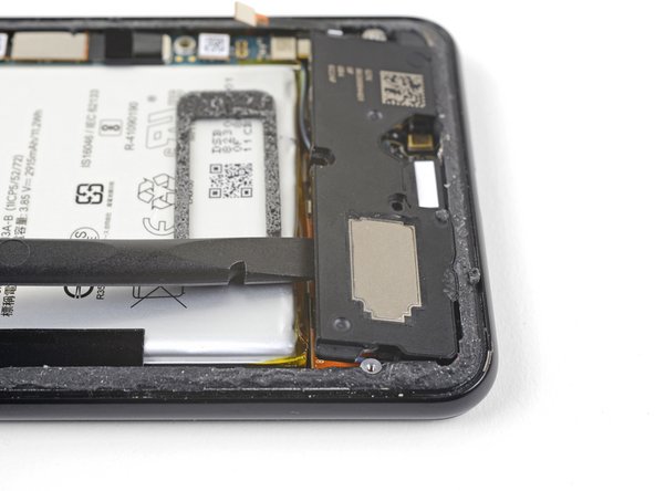
    • Insert the point of a spudger under the bottom right corner of the loudspeaker.

    • Pry up to loosen the loudspeaker from the phone.

  23. Deze stap is niet vertaald. Help het te vertalen

    : stap 23, afbeelding 1 van 2 : stap 23, afbeelding 2 van 2
    • Insert the point of a spudger under the top left corner of the loudspeaker.

    • Be careful not to puncture the battery with the spudger.

    • Pry up to loosen the loudspeaker.

  24. Deze stap is niet vertaald. Help het te vertalen

    : stap 24, afbeelding 1 van 2 : stap 24, afbeelding 2 van 2
    • Insert the flat end of the spudger under the top edge of the loudspeaker, towards the left edge.

    • Pry up to loosen the loudspeaker.

  25. Deze stap is niet vertaald. Help het te vertalen

    : stap 25, afbeelding 1 van 2 : stap 25, afbeelding 2 van 2
    • Remove the loudspeaker.

    • Before you install a replacement loudspeaker, check the adhesive gasket.

    • If it is in good condition, you can re-use the gasket. Make sure that the gasket does not cover the exit hole.

    • If the gasket is pulled out of place, remove it and replace the adhesive with a pre-cut strip or Tesa tape.

  26. Deze stap is niet vertaald. Help het te vertalen

    : stap 26, afbeelding 1 van 2 : stap 26, afbeelding 2 van 2
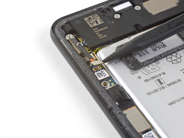
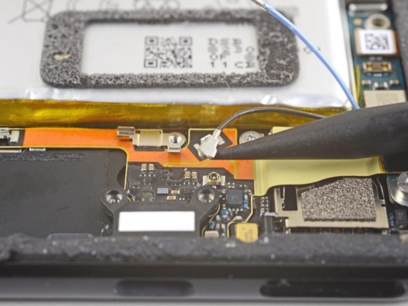
    • Use the point of a spudger to pry up and disconnect the blue antenna cable from its socket on the charging assembly.

  27. Deze stap is niet vertaald. Help het te vertalen

    : stap 27, afbeelding 1 van 2 : stap 27, afbeelding 2 van 2
    • Use the point of a spudger to carefully pry up and release the blue antenna cable from its grounding clips.

    • The cable is fragile and prone to breaking. If it feels like the wire is firmly clamped in place, use the point of a spudger to push the clip open slightly, then try again.

  28. Deze stap is niet vertaald. Help het te vertalen

    : stap 28, afbeelding 1 van 2 : stap 28, afbeelding 2 van 2
    • Use the point of a spudger to pry up and disconnect the black antenna cable from its socket near the USB-C port.

  29. Deze stap is niet vertaald. Help het te vertalen

    : stap 29, afbeelding 1 van 1
    • Carefully de-route both antenna cables and move them away from the charging assembly.

  30. Deze stap is niet vertaald. Help het te vertalen

    : stap 30, afbeelding 1 van 3 : stap 30, afbeelding 2 van 3 : stap 30, afbeelding 3 van 3
    • Use the point of a spudger to pry up and disconnect the charging assembly's connector from its motherboard socket, near the right edge of the phone.

    • Carefully peel the flex cable from the top of the SIM card reader.

  31. Deze stap is niet vertaald. Help het te vertalen

    : stap 31, afbeelding 1 van 2 : stap 31, afbeelding 2 van 2
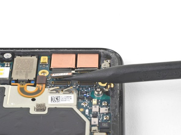
    • Use the flat end of a spudger to carefully pry up the black tape holding the display flex cable in place, near the right edge of the phone.

    • Do not use metal tools to pry, or you may damage the flex cable.

    • Use the flat end of a spudger to pry up and disconnect the display connector from the motherboard.

  32. Deze stap is niet vertaald. Help het te vertalen

    : stap 32, afbeelding 1 van 3 : stap 32, afbeelding 2 van 3 : stap 32, afbeelding 3 van 3
    • Whenever you use the spudger near the battery, be very careful not to puncture the battery.

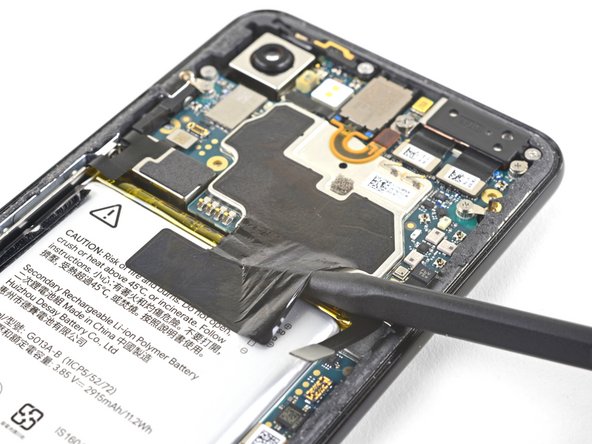
    • Slide the point of a spudger in the crevice underneath the black tape bridging across the battery and the motherboard.

    • Slide the spudger along the crevice to pry up the tape from the battery side.

    • Carefully peel the tape from the battery and fold it out of the way.

  33. Deze stap is niet vertaald. Help het te vertalen

    : stap 33, afbeelding 1 van 2 : stap 33, afbeelding 2 van 2
    • Use a spudger to pry up and disconnect the following seven press-fit connectors from their motherboard sockets:

    • External buttons connector

    • Top microphone connector

    • Earpiece connector

    • Left squeeze sensor connector

    • Screen connector

    • Right squeeze sensor connector

    • SIM tray connector

  34. Deze stap is niet vertaald. Help het te vertalen

    : stap 34, afbeelding 1 van 1
    • Use the flat of a spudger to carefully pry up and bend the earpiece speaker's flex cable upwards, out of the way of the motherboard.

  35. Deze stap is niet vertaald. Help het te vertalen

    : stap 35, afbeelding 1 van 2 : stap 35, afbeelding 2 van 2
    • Some of these screws hold very small grounding clips in place. Be careful not to lose these clips as you remove the screws.

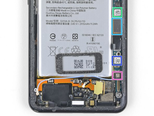
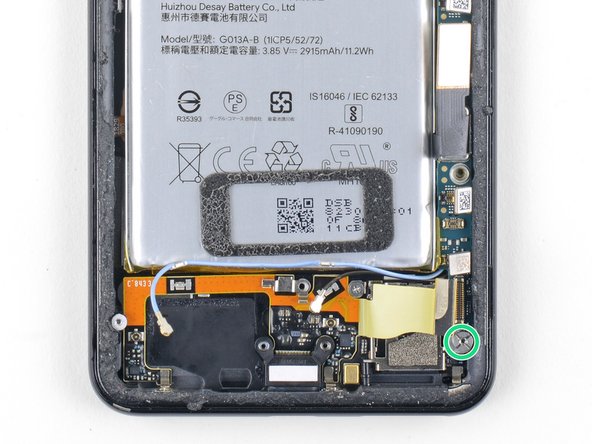
    • Remove the six screws securing the motherboard in place:

    • One 4.2 mm Phillips screw

    • Three 1.9 mm Phillips screws

    • One 4.3 mm Phillips screw

    • One 3.83 mm standoff screw

    • Standoff screws are best removed using a standoff bit. In a pinch, a small flathead screwdriver will do the job—but use extra caution to ensure it doesn't slip and damage surrounding components.

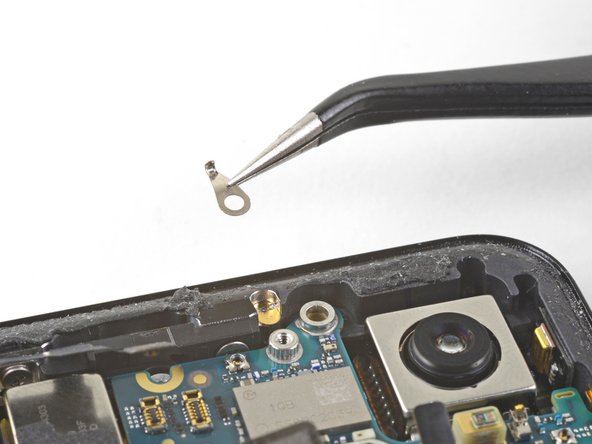
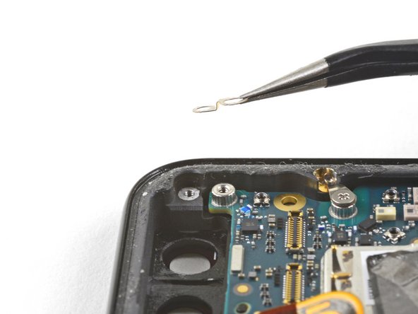
    • Remove and retain the three small metal grounding clips.

  36. Deze stap is niet vertaald. Help het te vertalen

    : stap 36, afbeelding 1 van 3 : stap 36, afbeelding 2 van 3 : stap 36, afbeelding 3 van 3
    • Carefully remove the antenna bracket from the top left edge of the phone.

    • To reinstall the small metal grounding clips:

    • Orient the clips such that the silver side is facing upwards.

    • The teardrop shaped clips should have their points facing towards the phone edge.

    • The double-holed clip dips downwards towards the frame's top-right screw hole.

  37. Deze stap is niet vertaald. Help het te vertalen

    : stap 37, afbeelding 1 van 2 : stap 37, afbeelding 2 van 2
    • Insert the point of a spudger near the top left corner of the motherboard, right below the rear-facing camera.

    • Pry up gently to loosen the motherboard, bending all flex cables away to accommodate for the movement.

    • If the motherboard feels firmly seated, check for any flex cables or screws that may still be connected.

  38. Deze stap is niet vertaald. Help het te vertalen

    : stap 38, afbeelding 1 van 2 : stap 38, afbeelding 2 van 2
    • Insert the spudger underneath the top edge of the motherboard and carefully pry up to loosen the motherboard.

    • The earpiece speaker's flex cable will press tightly against the motherboard. Take your time and carefully guide the motherboard around the flex cable.

  39. Deze stap is niet vertaald. Help het te vertalen

    : stap 39, afbeelding 1 van 2 : stap 39, afbeelding 2 van 2
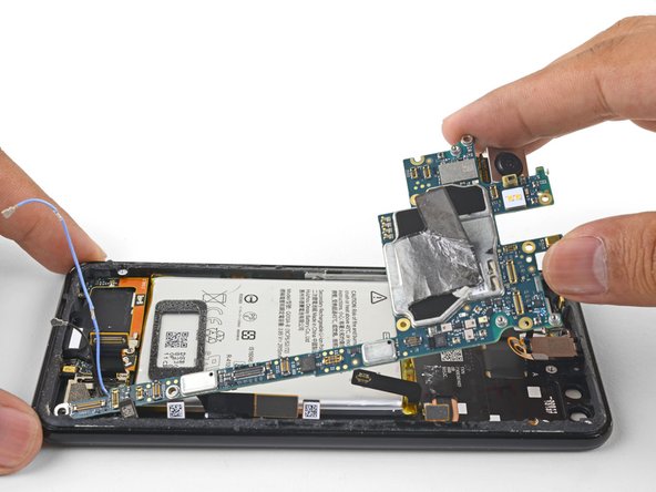
    • Lift the left edge of the motherboard and carefully swing upwards it towards the right. Carefully push any press connectors snagging the motherboard out of the way.

  40. Deze stap is niet vertaald. Help het te vertalen

    : stap 40, afbeelding 1 van 3 : stap 40, afbeelding 2 van 3 : stap 40, afbeelding 3 van 3
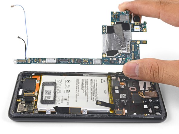
    • Carefully lift the top end of the motherboard away from the frame.

    • Remove the motherboard.

    • When you reinstall the motherboard, be careful not to trap any flex cable connectors underneath it.

    • It may be difficult to reposition the motherboard around the earpiece flex cable. You can gently pry up the earpiece speaker, install the motherboard, and reinstall the earpiece speaker.

  41. Deze stap is niet vertaald. Help het te vertalen

    : stap 41, afbeelding 1 van 3 : stap 41, afbeelding 2 van 3 : stap 41, afbeelding 3 van 3
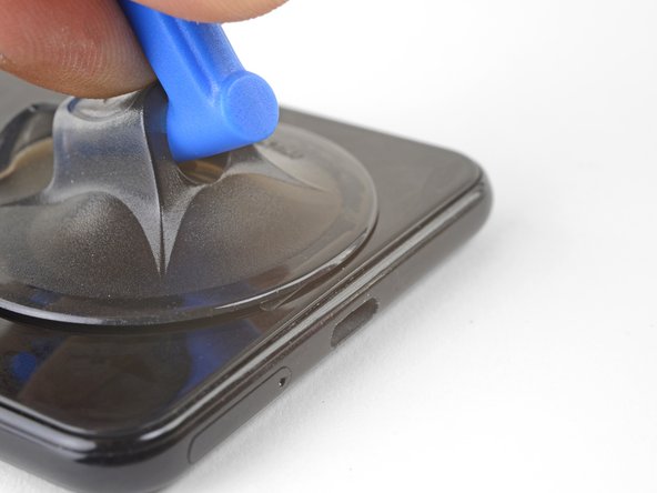
    • Apply a heated iOpener to the bottom edge of the screen for a minute.

    • Place a suction cup near the bottom edge of the screen, near the USB-C port.

    • Lift on the suction cup with strong, steady force to create a gap.

    • Depending on how aged your phone is, this may take significant force. If you are having trouble, apply more heat and try again.

    • You can also try heating and pulling up a long edge of the phone to gain access.

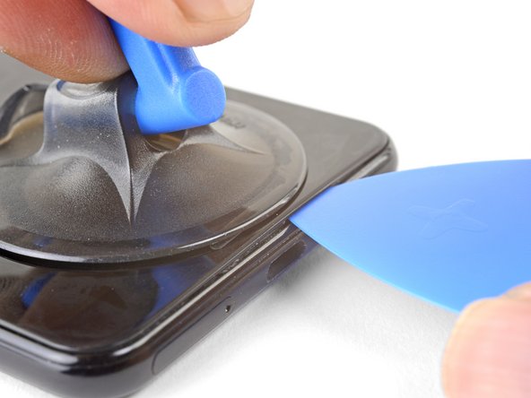
    • Insert an opening pick into the gap.

  42. Deze stap is niet vertaald. Help het te vertalen

    : stap 42, afbeelding 1 van 2 : stap 42, afbeelding 2 van 2
    • Slide the pick along the bezel to slice through the adhesive.

  43. Deze stap is niet vertaald. Help het te vertalen

    : stap 43, afbeelding 1 van 2 : stap 43, afbeelding 2 van 2
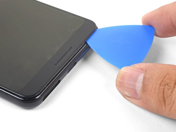
    • Continue heating edges with an iOpener and slicing the adhesive with an opening pick, until you've sliced through all of the adhesive.

  44. Deze stap is niet vertaald. Help het te vertalen

    : stap 44, afbeelding 1 van 2 : stap 44, afbeelding 2 van 2
    • Lift up and remove the front glass from the phone.

  45. Deze stap is niet vertaald. Help het te vertalen

    : stap 45, afbeelding 1 van 3 : stap 45, afbeelding 2 van 3 : stap 45, afbeelding 3 van 3
    • The remaining part of the screen is affixed to the phone frame by a large patch of adhesive.

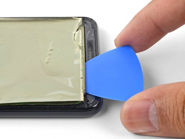
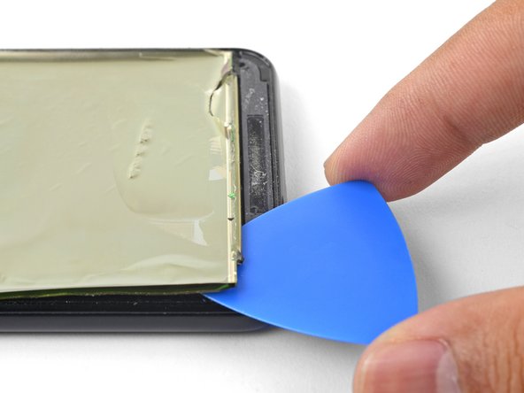
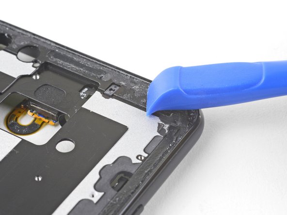
    • Insert an opening pick into the seam between the phone frame and the bottom edge of the screen remains.

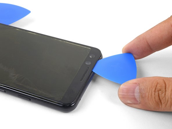
    • Pry along the edge to loosen the screen from the frame.

    • If you are having trouble, apply a heated iOpener over the screen to help loosen the adhesive.

  46. Deze stap is niet vertaald. Help het te vertalen

    : stap 46, afbeelding 1 van 3 : stap 46, afbeelding 2 van 3 : stap 46, afbeelding 3 van 3
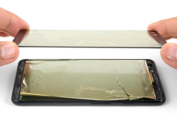
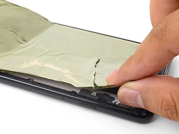
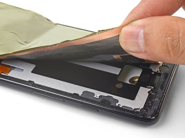
    • Continue applying heat and slicing along a screen edge until you've loosened enough material to be grasped with your fingers.

    • Grasp the edge with your fingers and slowly pull the screen remains away from the phone frame.

  47. Deze stap is niet vertaald. Help het te vertalen

    : stap 47, afbeelding 1 van 3 : stap 47, afbeelding 2 van 3 : stap 47, afbeelding 3 van 3
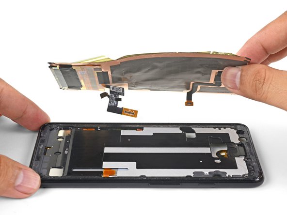
    • Thread the screen cable and digitizer cable out of their cutouts, then remove the display.

    • To install a replacement display assembly:

    • Clean all adhesive residue from the phone frame. Adhesive that's left behind may apply uneven pressure against the replacement screen and potentially damage it.

    • Apply a pre-cut adhesive, or double-sided tape to the phone frame's perimeter.

    • Peel all plastic liners from the back of the replacement screen to expose the adhesive.

    • Carefully thread the screen cable and the digitizer cable through the phone frame's cutouts.

    • Lay the screen onto the frame and place some books on top for an hour to help the screen adhesive bond to the frame.

    • During the boot-up process after reassembly, the screen will go through a calibration sequence. Do not touch the screen during this process, as it could result in improper touch calibration and create touch issues.

Eindstreep

26 andere personen hebben deze handleiding voltooid.

Arthur Shi

Lid sinds: 01/03/18

249.849 Reputatie

503 handleidingen geschreven

Team

iFixit Lid van iFixit

Staff

135 Leden

16.732 handleidingen geschreven

29 opmerkingen

To change only the screen glass… Do you have to disassemble the whole phone or just steps 39 to 42?

Thanks

Adrián García Estaún - Antwoord

Hi Adrián,

The OLED is bonded to the screen glass. Unlike LCDs, trying to remove the glass only will most likely destroy the OLED screen.

Arthur Shi -

How to differentiate between a pre-mounted and a non pre-mounted display? I don’t want to order the wrong part, hence the question.

Sid Mankad - Antwoord

The pre-mounted part will come with the frame, which is the majority of the phone body. The screen is already stuck affixed to the frame, but you would have to transfer everything else onto it. The display only part looks like a thin panel with adhesive on the back. It would look like this part.

Arthur Shi -

When buying a replacement screen do I need to buy it with a frame?

Abby Andam - Antwoord

Voeg opmerking toe

Weergavestatistieken:

Afgelopen 24 uren: 14

Afgelopen 7 dagen: 63

Afgelopen 30 dagen: 323

Altijd: 81,014