Inleiding
The mini motor for the Glade Automatic Spray Holder is not functioning. Rather than throw the entire casing and motor away, this guide will help you replace the motor.
Wat je nodig hebt
-
-
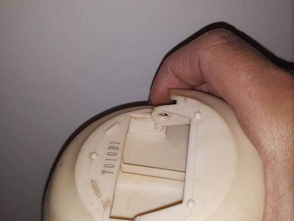
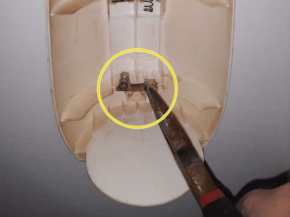
Press the button labelled glade to open the housing.
-
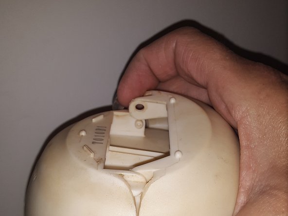
Locate the timer switch and slide it to off.
-
-
-
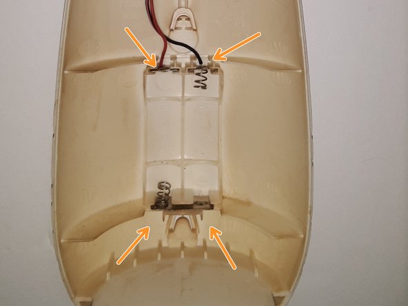
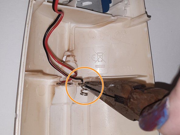
Use small needle nose pliers to gently remove each terminal. Check if any wires are disconnected or loose.
-
The terminals with negative connections (black wires) could have breaks or might have detached from the terminal base. Check for additional issues.
-
The bottom terminal is one piece instead of two pieces like the top ones.
-
-
-
Instructions for disassembly can be found with guide Glade Automatic Spray Holder SJC-180 Battery Terminal Replacement
-
-
-
There are 4 screws that need to be removed to expose the inner components (such as the motor). Use a Phillips head screwdriver to remove the screws. Gently pull the screws straight out to avoid disrupting the components you are exposing.
-
Once the cover is removed, take a picture to reference when you're reassembling the device. The larger electrical board is on the top. The plastic gears are easily moved out of their positions when removing cover and board.
-
-
-
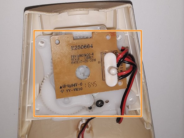
The first circuit board to inspect has the timer switch on it. This circuit board is the larger of the two that are part of the device.
-
The circuit board is held in place by 3 pegs. The pegs are plastic. This means you do not need special tools to remove the circuit board. It will pop off using your fingers.
-
Flip the board over to look for loose wires or any burnt spots. This one is okay.
-
-
-
It is best to remove plastic gears before flipping the plastic plate holding everything together. The gears will fall out. Start with the fan shape gear. No tools needed; each gear is held into place by pegs.
-
Next is the largest gear. It is centrally located.
-
Last is the medium size gear. Located towards the bottom left.
-
-
-
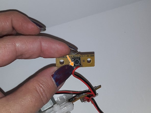
Solder the red wire back to the correct point on the circuit board. You'll be able to see the original factory solder point close to the edge of the board. It will be next to the black wire.
-
Once done with the solder, wait until it has cooled and pull gently to verify that it is securely attached to the circuit board.
-
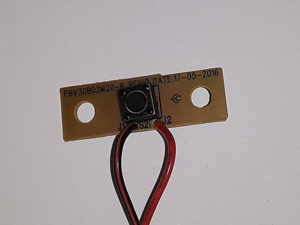
Finished the circuit board and wire reattachment.
-
-
-
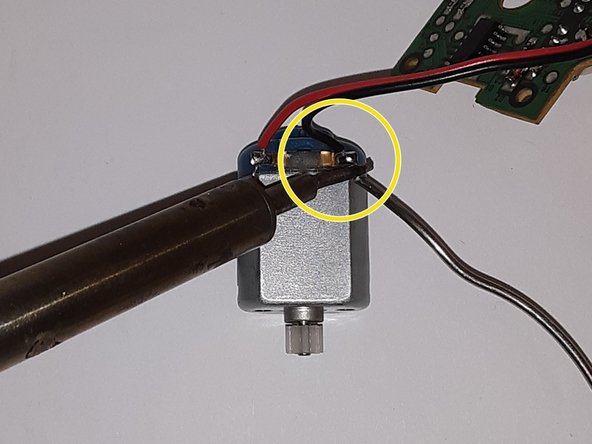
Once you follow the perquisites, locate the motor. It is metal with a blue top. A red wire and a black wire are attached to the blue top.
-
Flip the plastic plate holding the motor upside down and locate the 2 screws securing the motor to the plate.
-
Use a small Phillips head screwdriver to remove the screws. This will free the motor from the plate.
-
-
-
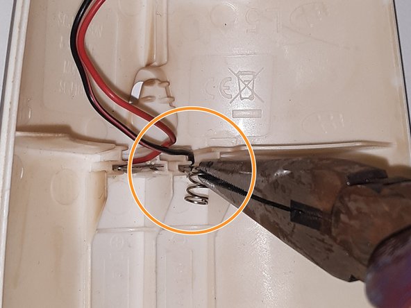
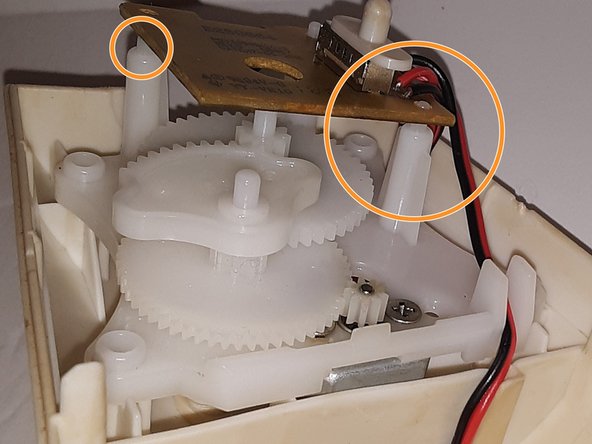
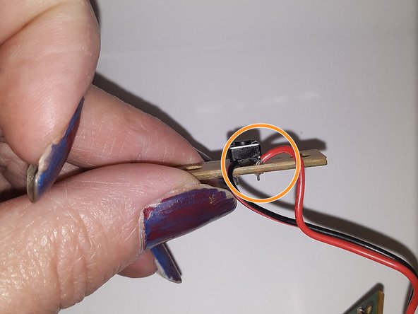
Cut the wires away from the old motor using the needle nose plier wire cutter, located next to the plier hinge (as seen in the red circle).
-
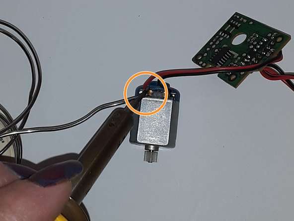
Attach the red wire to the new motor with the soldering iron and solder. The red wire will go to the left side of the motor face with a metal strip on the blue part.
-
Repeat with the black wire to the right side of the motor.
-


To reassemble your device, follow these instructions in reverse order.
To reassemble your device, follow these instructions in reverse order.

Team

Casper College, Team 5-5, Lareau Spring 2023 Lid van Casper College, Team 5-5, Lareau Spring 2023
CASC-LAREAU-S23S5G5
1 Lid
4 handleidingen geschreven