Deze versie kan foutieve bewerkingen bevatten. Schakel over naar de recentste gecontroleerde momentopname.
Wat je nodig hebt
-
Deze stap is niet vertaald. Help het te vertalen
-
Turn the multimeter so it is display side down.
-
Lift up the back stand of the device by putting your thumb in the curved well at the bottom of the device, so you have access to the two covered screws below.
-
-
Deze stap is niet vertaald. Help het te vertalen
-
Use your Phillips #2 Screwdriver to remove the four black 21 mm Phillips #2 screws.
-
-
Deze stap is niet vertaald. Help het te vertalen
-
Turn the Fluke 77 Series III Multimeter back over so that it is display side up.
-
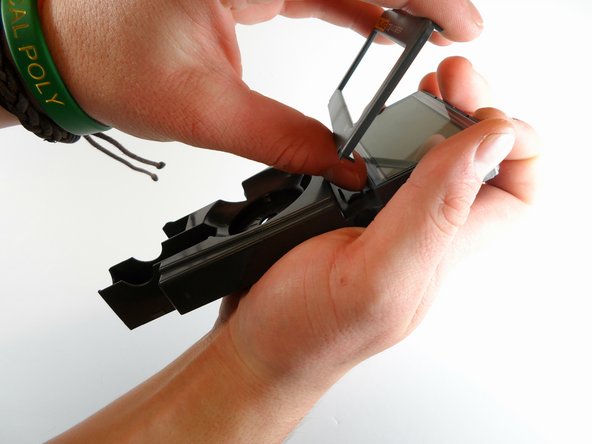
Pry the front panel from the back panel at the seam.
-
If the front panel does not come off easily, move a plastic opening tool along the seam until the panels separate completely.
-
-
-
Lokaliseer de 9V-batterij in de rechterbenedenhoek van het apparaat.
-
Neem de batterij uit de terminal.
-
-
-
Deze stap is niet vertaald. Help het te vertalen
-
Locate the fuses near the bottom left corner inside the device.
-
The .440 Amp fuse is located in the upper left hand fuse holder.
-
The 11 Amp fuse is located in the lower right hand fuse holder.
-
Lift the rounded edge of the fuse with one finger until that side is completely out of its holder.
-
-
Deze stap is niet vertaald. Help het te vertalen
-
Grab the lifted edge of the fuse between your thumb and forefinger and pull it the rest of the way out of the device.
-
Repeat steps 4 and 5 to remove the other fuse if you are replacing both fuses or if you are replacing a different part further on.
-
-
Deze stap is niet vertaald. Help het te vertalen
-
Locate the rubber range and hold buttons in the internal assembly. These are found just below the LCD screen on the left hand side.
-
Remove the rubber range and hold button part with your thumb and forefinger.
-
-
Deze stap is niet vertaald. Help het te vertalen
-
Locate the silver 7 mm screw found underneath the 11A fuse.
-
Using the Phillips #0 Screwdriver, unscrew and remove the silver 7 mm Phillips #0 screw that attaches the back panel to the internal cover.
-
-
Deze stap is niet vertaald. Help het te vertalen
-
Lift the grey internal cover out of the back panel.
-
-
Deze stap is niet vertaald. Help het te vertalen
-
Turn the internal assembly over so that the green circuit board (PCA) is visible.
-
Locate the five silver 11 mm Phillips #1 screws on the upper part of the circuit board that hold it to the the grey plastic internal cover.
-
-
Deze stap is niet vertaald. Help het te vertalen
-
Use the Phillips #1 Screwdriver to remove the five silver 11 mm Phillips #1 screws attaching the green circuit board to the grey plastic internal cover.
-
-
Deze stap is niet vertaald. Help het te vertalen
-
Carefully lift the circuit board up and away from the internal cover.
-
-
Deze stap is niet vertaald. Help het te vertalen
-
Turn the internal cover over with both hands.
-
Pry off the LCD screen bracket bordering the display.
-
-
Deze stap is niet vertaald. Help het te vertalen
-
Cover the LCD display with one of your hands.
-
Turn the internal cover over so that the LCD display is face down.
-
Slowly pull up the internal cover. The LCD display should fall right into your hand.
-


Annuleren: ik heb deze handleiding niet afgemaakt.
8 andere personen hebben deze handleiding voltooid.
Team

Cal Poly, Team 2-10, Amido Winter 2014 Lid van Cal Poly, Team 2-10, Amido Winter 2014
CPSU-AMIDO-W14S2G10
4 Leden
10 handleidingen geschreven
5 opmerkingen
Great job! Ive found that sometimes all it takes to get the LCD working again is to clean those pink rubber conductors and with isopropyl alcohol.
Good job .. can i make replacement display from fluk 179 to fluke 77 series 3 .. there are the same size with different model .. thank you
I just cracked the screen on my Fluke 79 III and this repair guide will be invaluable. If anyone can offer a part number for the screen or where I could buy one, I would be most appreciative.
FLUKE 1560856 for 175/177/179 Multimeters