Deze versie kan foutieve bewerkingen bevatten. Schakel over naar de recentste gecontroleerde momentopname.
Wat je nodig hebt
-
Deze stap is niet vertaald. Help het te vertalen
-
Place your device upside down and locate the battery compartment.
-
Find the Phillips head screw securing the battery cover in the bottom right hand corner of the device.
-
-
Deze stap is niet vertaald. Help het te vertalen
-
Slowly remove the battery cover with the iFixit opening tool.
-
-
Deze stap is niet vertaald. Help het te vertalen
-
Use the iFixit opening tool to carefully pry the battery out of the case.
-
After the old battery is removed replace it with a new battery facing the same direction as when the cover was opened.
-
-
Deze stap is niet vertaald. Help het te vertalen
-
Remove the following seven screws that secure the lower case to the DS Lite:
-
Three silver tri-wing screws (5mm long)
-
One black tri-wing screw (4mm)
-
Two gold Phillips screws (4mm)
-
One silver Phillips screw (3mm)
-
Do not remove the silver PH screw (3mm) in the battery compartment yet. It holds the main PCB in place.
-
-
-
Deze stap is niet vertaald. Help het te vertalen
-
On the front edge of the Nintendo DS between the headphone jack plug and volume controls remove the plastic insert (or cartridge) from the lower slot (Slot 2).
-
-
Deze stap is niet vertaald. Help het te vertalen
-
Flip the unit over so that it is facing right-side up.
-
Use a spudger to pry open the gap between the bottom case and the front panel. Work all the way around the case until the panel is free.
-
Avoid touching the L and R shoulder buttons, because they easily detach and are difficult to reassemble. Keep the bottom case flat against your workbench to help hold the shoulder buttons in place.
-
-
Deze stap is niet vertaald. Help het te vertalen
-
Carefully separate the two pieces by hand.
-
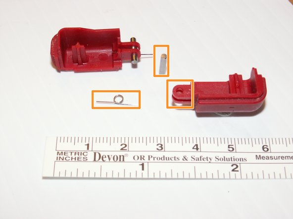
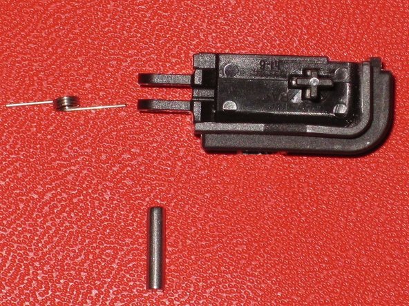
The two shoulder buttons are made up of three pieces -- the plastic button, a pin, and a spring. If they accidentally pop out while you are working, study the picture and make sure you put the spring in the correct position.
-
-
Stap 8
Voorzichtig: stap 8 komt van een handleiding die in bewerking is.
Deze stap is niet vertaald. Help het te vertalen
-
After taking the bottom case off, remove two Phillips #00 screws that secure the logic board to the plastic case.
-
-
Deze stap is niet vertaald. Help het te vertalen
-
Locate the small ribbon cable that connects the touch screen to the logic board.
-
Using a pair of tweezers, flip the black plastic latch up to release the cable.
-
Gently pull the cable straight out (towards the edge of the case).
-
-
Deze stap is niet vertaald. Help het te vertalen
-
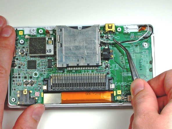
Locate the black and white cables that are attached to the logic board and WiFi module.
-
Using metal tweezers, gently disconnect the wires by pulling them away from the logic board and underneath the card slot.
-