Deze versie kan foutieve bewerkingen bevatten. Schakel over naar de recentste gecontroleerde momentopname.
Wat je nodig hebt
-
Deze stap is niet vertaald. Help het te vertalen
-
Case back removed from tablet
-
Remove the back with your fingernails, popping it open between the black border, and the plastic backing.
-
Be careful near the buttons and headphone jack.
-
-
Deze stap is niet vertaald. Help het te vertalen
-
Start by taking the screws from around the frame off.
-
Then remove the screws from this PCB
-
If you are replacing screen components, skip to step 7
-
Remove the little foam pads from the two connectors on the PCB These are for the digitizer
-
Flip up the releases on the plugs to pull out the ribbon cable. (I will show some more detailed pictures of the same process on other connectors.
-
-
Deze stap is niet vertaald. Help het te vertalen
-
Note the large copper heatsink. DO NOT pull this off.
-
There are a couple connectors underneath you will have to detach. They have flip up releases, hopefully you can see it.
-
-
-
Deze stap is niet vertaald. Help het te vertalen
-
First two are under the copper plate.
-
Next is at the bottom of the tablet.
-
-
Deze stap is niet vertaald. Help het te vertalen
-
Overview
-
Disconnect Sound connector.
-
Unscrew remaining PCBs
-
carefully unplug battery connector (under copper plate)
-
-
Deze stap is niet vertaald. Help het te vertalen
-
You'll have to (CAREFULLY) pop the power button (and maybe volume button) out of place so you do not rip the ribbon cable when removing the PCB. I used a tiny flat-head screwdriver.
-
-
Deze stap is niet vertaald. Help het te vertalen
-
Pic 1 - PCBs removed. Screen assembly and frame only.
-
Pic 2 - Screen assembly only.
-
Carefully peel silver tape off of black tape.
-
Starting at the right (in the picture) peel up the black tape. Be careful! The power ribbon cable for the backlight is hidden under at the left side. See next step for location of connection.
-
-
Deze stap is niet vertaald. Help het te vertalen
-
Pic 1 - LCD (left) backlight panel (right)
-
Pic 2 - LCD PCB, note backlight connector at right
-
Pic 3 - Backlight panel connector.
-
-
Deze stap is niet vertaald. Help het te vertalen
-
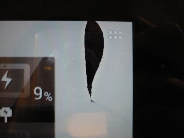
Be careful when removing LCD and when reassembling tablet. not sure when it happened, but apparently I was not careful enough when putting it back together, and this happened. Works perfectly fine otherwise. (Heat gun was not used).
-


Annuleren: ik heb deze handleiding niet afgemaakt.
17 andere personen hebben deze handleiding voltooid.
30 opmerkingen
So you are on step 7?
The digitizer is the whole front panel. The LCD is sandwiched between that and the backlight. (The big white panel)
Around the edge, the backlight sort of clips into the frame. Try using a small blade screwdriver to pop the clips.
B0NK3R5 -
OK i found the problem an done the rest but the tablet didnt start. I think ther is a problem with the cabel´s but i can´t find it. When i push 2 cabels on the backside the screen works but the Touch didn´t work . What is the Problem ? I have buyed this Part
http://www.ebay.de/itm/321001110973?ssPa... . It is the right part for my Asus TF 300 but why zhe touch doesent work
Did you connect the ribbon cables to the main board?
B0NK3R5 -