Deze handleiding heeft recentere wijzigingen. Schakel over naar de nieuwste niet-geverifieerde versie.
Inleiding
This guide will show you how to remove all the necessary pieces in order to reach and disconnect the Lens and replace it.
Wat je nodig hebt
-
-
Use the Phillips #00 screwdriver to remove the two screws located on the right side of the camera.
-
-
-
Use the Phillips #00 screwdriver to remove the three screws on the bottom of the camera.
-
Use the plastic opening tool to lift the cover containing the patent information off.
-
-
-
Place the plastic opening tool in the crack between the metal circle and the black piece on the left.
-
Slide the black cover and lift to remove.
-
-
-
The first picture shows how the left side of the camera looks once we remove the side piece.
-
Use the Phillips #00 screwdriver to remove the two screws on this left side.
-
Flip your camera to the right side where we removed the first two screws.
-
Use the plastic opening tool into the crack and lift in order to loosen that side of the shell. Loosening one side makes removing the entire shell easier.
-
-
-
Once the side is loose, apply a small amount of force to remove the shell.
-
-
-
Removing the outer shell will expose the motherboard (the green chip).
-
Carefully grab the motherboard and flip it over.
-
Locate the ribbon wire protruding from the motherboard. Grip the wire as close to the white square as possible and slightly pull it to disconnect it from the wire.
-
-
-
Remove the LCD Screen to separate the metal frame connecting the screen to the camera.
-
Gently pull the metal frame away, keeping in mind that the right end of the screen is attached by a ribbon wire.
-
Slowly remove the metal frame until it fully pops off.
-
-
-
Flip the metal screen to be facing down. There will be a small black clip on the white connector that will allows the ribbon wire to be removed.
-
Carefully lift the black clip and slide the ribbon out in order to remove the LCD screen.
-
-
-
The first set of screws you should remove are found on the right side of the camera, when the LCD screen is facing you.
-
Grab your Phillips #00 screw driver from your tool kit. Use the screw driver to remove the two screws located on the right side of the camera.
-
-
-
Now flip your camera over so that the bottom of the camera is facing up. Notice that there are three screws.
-
Grab your Phillips #00 screwdriver from the tool kit. Use the screwdriver to remove the three screws on the bottom.
-
Grab your plastic opening tool and stick it in between the crack to lift the cover containing the patent information off.
-
-
-
Next, with the same plastic opening tool, stick it in the crack between the metal circle and the black piece on the left, in order for it to be removed.
-
Once you slide the plastic opening tool in between the crack, slide the black cover and lift in order for it to be removed.
-
-
-
The first picture shows how the left side of the camera looks once we remove the side piece.
-
Notice that there are now two screws that need to be removed. Grab your Phillips #00 screwdriver and remove the two screws.
-
-
-
Once the side is loose, apply a small amount of force to remove the shell
-
Make sure to push each side off individually so that you do not break any piece of the camera.
-
It is also important that you keep the battery compartment open to make this step easier.
-
-
-
After you remove the outer shell, you will see that the green chip, known as the motherboard is now exposed.
-
Carefully grab the motherboard and proceed to flip it over.
-
Grab the ribbon that connects the motherboard to the camera. Grip the ribbon wire as close to the white piece as possible. Slightly pull it to disconnect it from the wire.
-
-
-
In order to remove the LCD Screen we separate the metal frame that connects the screen to the camera.
-
Pull the metal frame from left to the right. As you move towards the right, you will notice on the right end, the screen is attached by a ribbon wire.
-
This may be the most challenging step. Slowly remove the metal frame, and eventually it will pop off.
-
-
-
Flip the metal screen over, so that the screen is facing down
-
You will see a small black clip on the white connector that will allow you to remove the ribbon wire.
-
Carefully lift the black clip and slide the ribbon out.
-
The LCD Screen should now be removed.
-
-
-
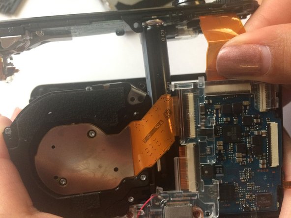
Grab your Phillips #00 tool and remove the screw located at the top middle of the camera.
-
There is a ribbon wire on the top right. Make sure to disconnect the ribbon wire as you did in the previous step.
-
Slowly and carefully pull up.
-
-
-
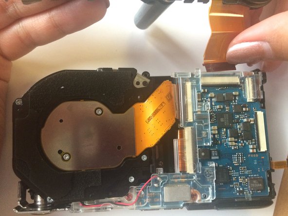
Pull off front outer shell by pushing off from left side.
-
-
-
Remove the two orange screws located under the lens.
-
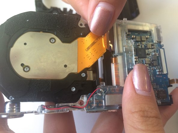
Remove the plastic by grabbing the right side of the camera and pushing it away in order for the plastic to come out.
-
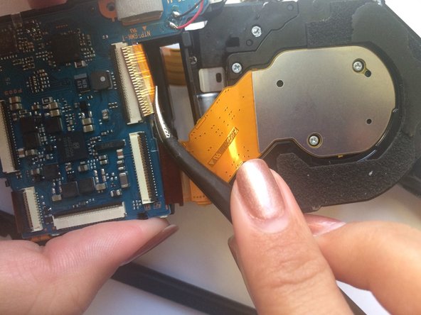
By removing the plastic, we can now easily remove the ribbon wires by lifting the black clip and sliding ribbon wire out. Use tweezers if necessary.
-
-
-
Once the ribbons are detached, the lens is now completely detached from camera and can be replaced.
-


To reassemble your device, follow these instructions in reverse order.
To reassemble your device, follow these instructions in reverse order.
Annuleren: ik heb deze handleiding niet afgemaakt.
Één andere persoon heeft deze handleiding voltooid.
Team

USF Tampa, Team 6-2, Brown Winter 2015 Lid van USF Tampa, Team 6-2, Brown Winter 2015
USFT-BROWN-W15S6G2
3 Leden
6 handleidingen geschreven