Inleiding
Gebruik deze handleiding om het scherm van een Asus ROG G751JL te verwijderen of te vervangen.
Wat je nodig hebt
-
-
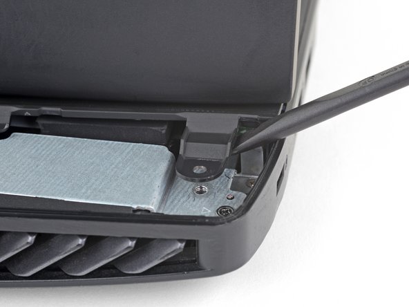
Gebruik een openingstool om de kleine rubberen afscherming in de rechter bovenhoek van de RAM-ingang omhoog te duwen.
-
-
-
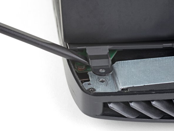
Steek de brede kant van een openingsplectrum in een nieuwe plek in de naad tussen de RAM-deur en de computer.
-
Wrik de deur omhoog om de klemmen het dichtst bij je plectrum los te maken.
-
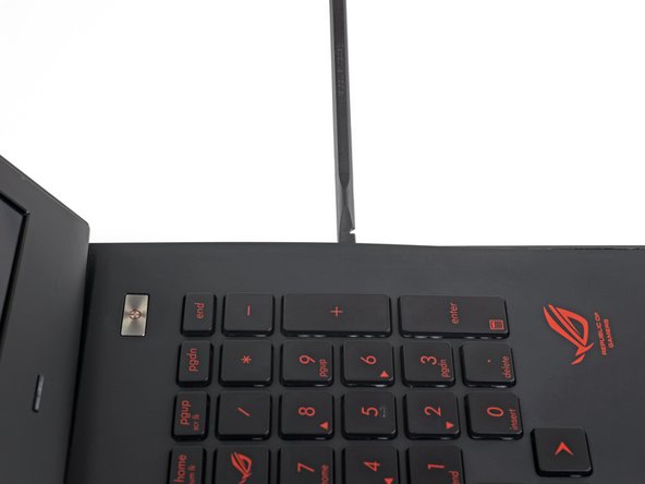
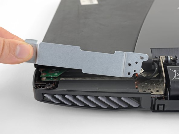
Schuif je plectrum door de naad rondom de deur en wrik de deur af en toe omhoog totdat alle klemmen die de deur bevestigen los zijn gekomen.
-
-
-
Verwijder de 5.2 mm lange Phillips #00 schroef die de optische schijf bevestigt.
-
-
-
Gebruik de punt van een spudger om de elf rubberen sluitingen die over de schroeven in de onderkant van de laptop zijn geplaatst, eruit te duwen.
-
-
-
Verwijder 18 Phillips #00 schroeven met de volgende lengtes:
-
Acht 8.8 mm lange schroeven
-
Zeven 5.2 mm lange schroeven
-
Drie overige schroeven
Step 9: on my model the 2 lower left most red 8.8 mm screws appear to be 5.2 mm orange screws.
-
-
-
-
Kantel de laptop op z'n rechterkant.
-
Gebruik een openingsplectrum om de linker- en rechterkant van de bescherming over de batterij uit de laptop los te krijgen, net zo ver totdat je beide kanten met je vingers kunt vastpakken.
-
-
-
Trek de speakeraansluitingen in een rechte beweging uit elkaar om de speakerkabel los te koppelen.
-
-
-
Op het scherm van de laptop tot een hoek van ongeveer 90°.
-
Gebruik een spudger om een van de uitstulpingen aan de achterkant van de bovenste behuizingsmodule, die de schroefopeningen bevatten, omhoog te duwen.
-
Herhaal deze procedure bij de andere uitstulping.
-
-
-
Gebruik de punt van een spudger om de kleine sluitklem op de ZIF-aansluiting van de backlightkabel van het toetsenbord omhoog te klappen.
-
Trek de kabel voorzichtig uit het contact.
-
-
-
Herhaal de vorige stap bij het toetsenbord, de trackpadknoppen en de trackpadkabels, die allemaal op zijn verbonden door middel van ZIF-aansluitingen.
Gently pry up onwards each of the white plastic connector just above the ribbon cable (or near the gray rib on the wider ribbon cable).
-
-
-
Om de batterij los te koppelen, trek je de batterijkabel weg van de aansluiting, parallel aan hoe de kabels lopen.
-
-
-
Pak de zwarte tape die aan de schermkabel is bevestigd vast en trek deze in een rechte beweging omhoog om de schermkabel los te koppelen.
Before trying to remove the display connector, gently lift tape holding speaker cable and temporarily push cable aside to allow more access to the tape holding the display cable. Then proceed to lift the display cable.
-
-
-
Til de monitor in een rechte beweging omhoog en verwijder deze.
Please add the step to unplug both wifi antenna cables and the display connector before removing the monitor. Both just pop up.
Hi this comment is correct. This guide completely skips the important step of removing and replacing the wifi cables. Without this step the computer is unable to retain its wifi functions
ggrinste -
How to replace the lcd?
I have to agree with Sam Torres on this. I reached the same spot where the screen was off, but then which wire goes to which connector. The picture is too fuzzy to be completely clear. It looks like the one further to the back (lcd screen) might be the white one and the one closer to the front of the laptop (touchpad) might be teh black one but the only way to tell is to assemble everything and then get the bad or good news.
-


Om je toestel weer in elkaar te zetten, volg je deze instructies in omgekeerde volgorde.
Breng je e-afval naar een R2 of e-Stewards gecertificeerde recycler.
Ging je reparatie niet zoals gepland? Check dan onze antwoordencommunity voor hulp bij het oplossen van je probleem.
Om je toestel weer in elkaar te zetten, volg je deze instructies in omgekeerde volgorde.
Breng je e-afval naar een R2 of e-Stewards gecertificeerde recycler.
Ging je reparatie niet zoals gepland? Check dan onze antwoordencommunity voor hulp bij het oplossen van je probleem.
Annuleren: ik heb deze handleiding niet afgemaakt.
4 andere personen hebben deze handleiding voltooid.
Met dank aan deze vertalers:
100%

Thomas Keulemans helpt ons de wereld te herstellen! Wil je bijdragen?
Begin met vertalen ›
Team

USF Tampa, Team 2-1, Sullivan Fall 2016 Lid van USF Tampa, Team 2-1, Sullivan Fall 2016
USFT-SULLIVAN-F16S2G1
4 Leden
20 handleidingen geschreven
3 opmerkingen
You have left out TWO very important steps. A) tools needed: a - fine tweezer and b - magnifier glass [ and a lot of patience }.
With the open computer facing you. On the left side two gold electrode wires connect to the motherboard, note the wire placement of the two.
On the right side there is a ribbon connector on the right side. NOTE, when the monitor is lifted out, these will COME OFF. If you are a notice, you will be lost. My guess the new monitor will have these connector. To rebuild: place the set screws for the monitor and then the left and right rear brackets. Go back to front view and insert the back ribbon connector to the motherboard on the right backside. Take a break. Use the magnifier glass and tweezer and attempt to align the SMALL ELECTRODE heads. When aligned they can be pressed on, a light snap will be heard. Please be carefull. This step took me 1 hour. After these steps, continue re-assembly.
Regard,
D C
Would the display connector be the same for the touchscreen model? Or is there an additional cable/different connector?
TUTO remarquable de clarté