Ga door naar hoofdinhoud

Deze versie kan foutieve bewerkingen bevatten. Schakel over naar de recentste gecontroleerde momentopname.

Wat je nodig hebt

  1. Deze stap is niet vertaald. Help het te vertalen

    : stap 1, afbeelding 1 van 3 : stap 1, afbeelding 2 van 3 : stap 1, afbeelding 3 van 3
    • Using a metal spudger, push down between the edge seals on the base and pry off the base.

    • Do not confuse the top thin layer of rubber with the thick palette that needs to be removed.

    • This may require substantial force.

  2. Deze stap is niet vertaald. Help het te vertalen

    : stap 2, afbeelding 1 van 3 : stap 2, afbeelding 2 van 3 : stap 2, afbeelding 3 van 3
    • Use the T-10 bit from the iFixit tool kit to unscrew the four 1.4 inch corner screws on top of the first layer.

    • There are 4 washers to go with each of the screws.

  3. Deze stap is niet vertaald. Help het te vertalen

    : stap 3, afbeelding 1 van 1
    • Lift and remove the full frame.

  4. Deze stap is niet vertaald. Help het te vertalen

    : stap 4, afbeelding 1 van 2 : stap 4, afbeelding 2 van 2
    • Lift and remove the speaker.

    • Carefully match the outlets on the speaker with the outlets on the motherboard.

  5. Deze stap is niet vertaald. Help het te vertalen

    : stap 5, afbeelding 1 van 2 : stap 5, afbeelding 2 van 2
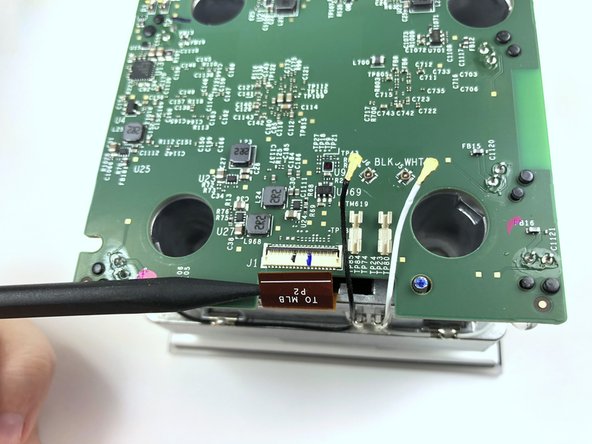
    • Lift the black latch by gently prying up with the flat end of the Spudger.

    • Detach the copper tap by pulling it out.

  6. Deze stap is niet vertaald. Help het te vertalen

    : stap 6, afbeelding 1 van 2 : stap 6, afbeelding 2 van 2
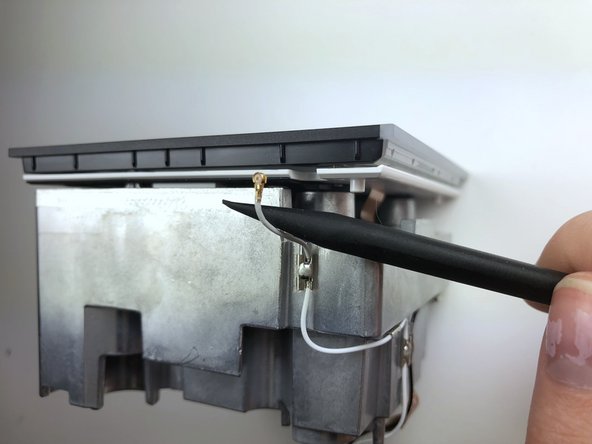
    • Use the pointed end of the Spudger to carefully detach the black and white wires from the motherboard.

    • Make sure all three attachments (the copper tab and both wires) are fully disconnected before continuing.

  7. Deze stap is niet vertaald. Help het te vertalen

    : stap 7, afbeelding 1 van 2 : stap 7, afbeelding 2 van 2
    • Gently pry the motherboard up and off.

  8. Deze stap is niet vertaald. Help het te vertalen

    : stap 8, afbeelding 1 van 3 : stap 8, afbeelding 2 van 3 : stap 8, afbeelding 3 van 3
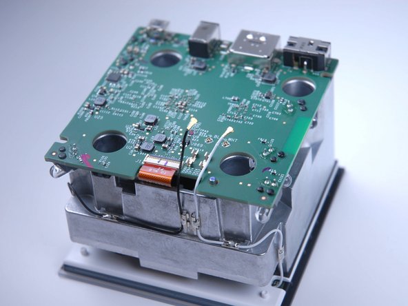
    • Detach the wires from the opposite end of the frame using the flat end of the Spudger.

    • You can’t see where the wires are attached because it is hidden underneath the white frame.

    • Make sure both wire attachments are fully disconnected before continuing.

  9. Deze stap is niet vertaald. Help het te vertalen

    : stap 9, afbeelding 1 van 2 : stap 9, afbeelding 2 van 2
    • Pry apart the black plastic face from metal frame.

    • This requires substantial force.

    • Be careful not to tear connecting copper tab.

  10. Deze stap is niet vertaald. Help het te vertalen

    : stap 10, afbeelding 1 van 2 : stap 10, afbeelding 2 van 2
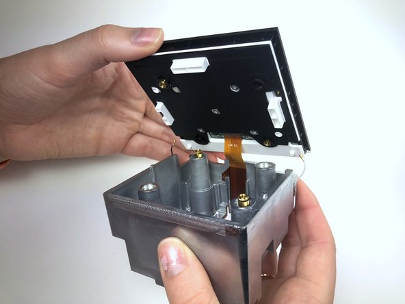
    • Lift the black latch to detach the copper tab by gently prying with the Angled Tweezers.

    • Use the Angled Tweezers to carefully pull out the copper tab.

  11. Deze stap is niet vertaald. Help het te vertalen

    : stap 11, afbeelding 1 van 2 : stap 11, afbeelding 2 van 2
    • Unscrew the five T-6 quarter inch screws.

  12. Deze stap is niet vertaald. Help het te vertalen

    : stap 12, afbeelding 1 van 2 : stap 12, afbeelding 2 van 2
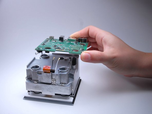
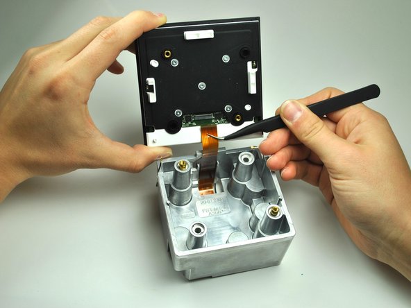
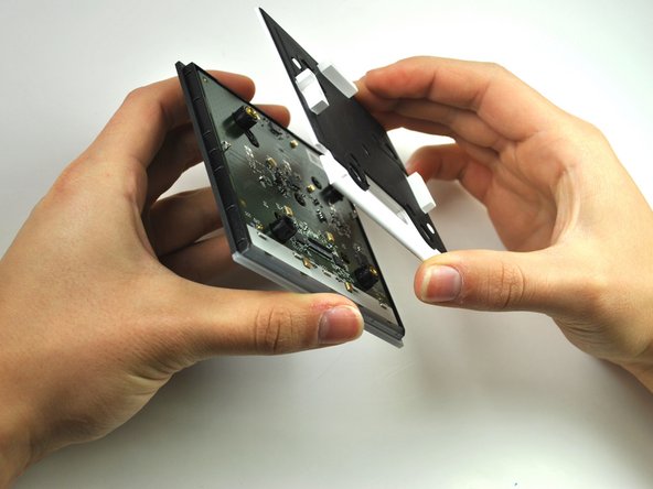
    • Lift and remove white the frame to reveal the circuit board.

  13. Deze stap is niet vertaald. Help het te vertalen

    : stap 13, afbeelding 1 van 3 : stap 13, afbeelding 2 van 3 : stap 13, afbeelding 3 van 3
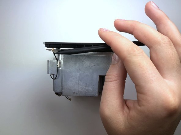
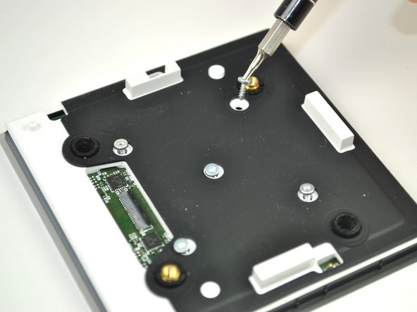
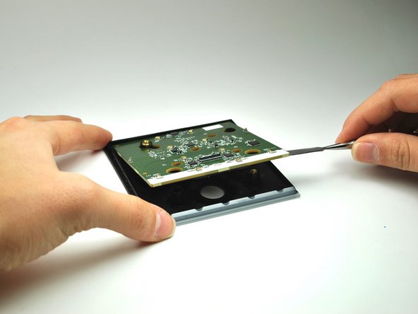
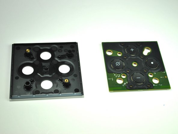
    • Using a the Metal Spudger, pry up the circuit board to reveal a rubber button panel.

  14. Deze stap is niet vertaald. Help het te vertalen

    : stap 14, afbeelding 1 van 2 : stap 14, afbeelding 2 van 2
    • Peel back the rubber button casing.

    • Pay close attention to the orientation of the rubber casing.

Eindstreep

Één opmerking

A suggestion for step 8: the antenna wires are not soldered to the aluminum heatsink; they are soldered to small clips that are easily popped off from the heatsink. I found it much easier to pop off all the clips and free the antenna wires from the heatsink than try to remove the antenna connectors from the top circuit board while it is still attached to the frame. After removing the top circuit board from the frame, it’s then much easier to remove the antenna connectors.

Phil G - Antwoord

Voeg opmerking toe

Weergavestatistieken:

Afgelopen 24 uren: 2

Afgelopen 7 dagen: 11

Afgelopen 30 dagen: 22

Altijd: 2,610